

Product Images are shown for illustrative purposes only and may differ from the actual product.


Radiolink AT9S Pro 10/12 Channels 2.4GHz RC Transmitter and Receiver Mode 2
 Store Pickup Available!
 Free Ship Over 5000 BDT
 Quality Product
 No Warranty
 No Replacement
Radiolink AT9S Pro 10/12 Channels 2.4GHz RC Transmitter and Receiver Mode 2
The latest price of Radiolink AT9S Pro 10/12 Channels 2.4GHz RC Transmitter and Receiver Mode 2 in Bangladesh is BDT 17,500 You can buy the Radiolink AT9S Pro 10/12 Channels 2.4GHz RC Transmitter and Receiver Mode 2 at best price from our RoboticsBD or visit RoboticsBD Office.
|
Please note that the product information provided on our website may not be entirely accurate as it is collected from various sources on the web. While we strive to provide the most up-to-date information possible, we cannot guarantee its accuracy. We recommend that you always read the product labels, warnings, and directions before using any product. |
|
Product Images are shown for illustrative purposes only and may differ from the actual product. |
Reference: RBD-0172
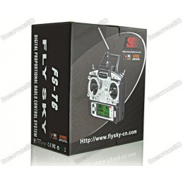
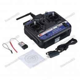
FlySky FS-T6 2.4ghz Digital Proportional 6 Channel Transmitter & Receiver System FlySky Introduces its newest 6 channel 2.4GHz system, The FS-T6. After years of success with the CT6B, FlySky presents the new FS-T6 with loads of cool and convenient features making the operation of this transmitter simple and instinctive.
Reference: RBD-0718
Model Type: Digital Radio Transceiver. Sensitivity: 1024. Bandwidth: 500 kHz. Default Operating Mode: Mode 2 (Left-Hand Throttle). No. of Channels: 6. Operating Voltage: 12V DC (1.5AA x 8 Battery) (not included).
Reference: RBD-0957
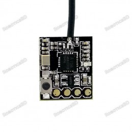
Item name: FS-RX2A Radio receiver Channel: 10 RF Range: 2.408-2.475GHZ Number of bands: 135 RX Sensitivity: -92dBm 2.4GHz protocol: AFHDS 2A Signal output: IBUS, PPM Compatible Transmitter: All AFHDS 2A Transmitter, Ex.: FS-I6, FS-I6X, FS-I6S, FS-TM8, FS-TM10, FS-I10.
Reference: RBD-2167
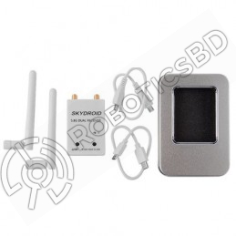
Skydroid 5.8G 150CH Full Channel UVC Dual Antenna Control Receiver OTG FPV Receiver Designed for Android phones with UVC support and OTG compatibility Dual antenna design for improved signal stability Channel waveform display and channel adjustment button added for convenience Supports audio playback through the app Automatic scanning mode activated by...
Reference: RBD-1023
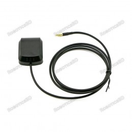
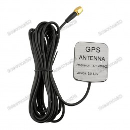
Frequency (MHz) 1575 +/- 5 MHz Gain > 28 dBi (with LNA) Impedance (Ω) 50 Ω VSWR < 1.5 Polarization RHCP Power Handling (W) 50 watts Cable Length: 3Meter Connector: SMA-Male
Reference: RBD-0729
Frequency (MHz) 1575 +/- 5 MHz Gain > 28 dBi (with LNA) Impedance (Ω) 50 Ω VSWR < 1.5 Polarization RHCP Power Handling (W) 50 watts Cable Length: 3Meter Connector: SMA-Male
Reference: RBD-0201
QUICK OVERVIEW Transmitter: FS-TH9X Upgrade with FS-RM003 2.4GHz Module Receiver: FS-IA10B Default Mode: Mode-2 Input Power: 12V DC (1.5V x 8 AAA Battery) Bidirectional System Frequencies-Hopping Omni-directional High Gain Antenna Low Power Consumption
Reference: RBD-0719
Bandwidth (KHz): 500. RF Range (GHz): 2.40 ~ 2.48. No. of channels: 6. Remote controller weight (gm): 400. Power: 6V (1.5V AA*4). Antenna Length: 26mm * 2 (dual antenna). Transmitting Power: ≤ 20dBm. RF Receiver Sensitivity: -105dbm. RoboticsBD
Reference: RBD-0931
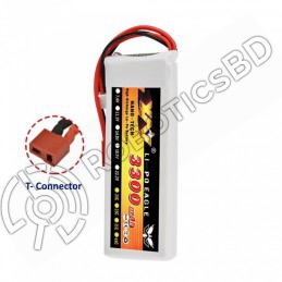
Weight : 190 gm Voltage: 11.1V Capacity: 3300mAh Cell Type: Li-polymer Configurations: 3S Continuous Discharge Rate: 25C Max Burst Rate: 90C Discharge(Output) Lead: T Plug Connector Charging(Balancing) Lead: JST-XHR Wire Length: 100mm Operating Temperature Range: -20℃to 60℃ PVC color: Silver and Black
Reference: RBD-0300
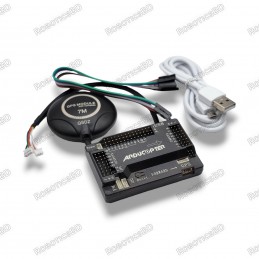
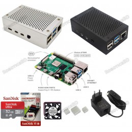
Model: APM 2.8 Arducopter APM 2.8 Flight Controller Input Voltage (V): 12-16 V. Arducopter APM 2.8 Flight Controller Processor: ATMEGA2560 and ATMEGA32U-2 Arducopter APM 2.8 Flight Controller Dimensions (mm) LxWxH: 70 x 45 x 15 Ublox NEO 7M GPS Tracking sensitivity: 161 dBm Ublox NEO 7M GPS Capture sensitivity : 148 dBm Ublox NEO 7M GPS cold start time:...
Reference: RBD-0141
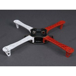
Wheelbase: 450mm Material: Glass Fiber + Polyamide-Nylon Moter Mounting Hole Diameter: 3 mm Arm Size: 220 x 40 (LxW) mm Arm mounting holes (on frame): 3 mm Arm mounting holes (on arm): 2 mm
Reference: RBD-0743
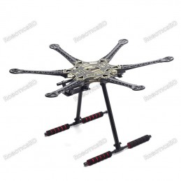
Wheelbase: 550mm Weight: 550g/720g(without/with gimbal) Adopts S800 upward tilt arm design – Plastic injection moduling Ensures hardness and lighter weight – Brushless gimbal compatible for FPV It comes with PCB center board of soldered The arm equips support ridges for better and faster forward flight. Features pre-threaded brass sleeves.
Reference: RBD-1260
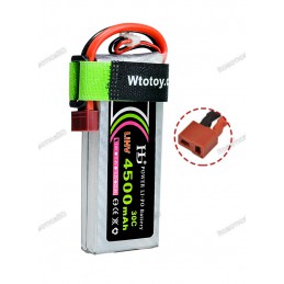
Model No: HJ Power Lipo Battery 4500mAh 11.1V 3S Voltage: 11.1V Max Continuous Discharge: 35C Balance Plug: JST-XH Discharge Plug: XT-60
Reference: RBD-1543
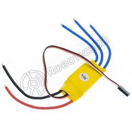
Constant Current: 30A (Max 40A<10s). BEC: 5V 3A. Input Voltage: 11.1 ~ 11.7 V. Li-Po battery: 2S ~ 3S. Ni-MH 4-10 CELLS Auto Detect. Current stock is without connector
Reference: RBD-0022
This is the HC-SR04 ultrasonic distance sensor. This economical sensor provides 2cm to 400cm of non-contact measurement functionality with a ranging accuracy that can reach up to 3mm. Each HC-SR04 module includes an ultrasonic transmitter, a receiver and a control circuit. There are only four pins that you need to worry about on the HC-SR04: VCC (Power),...
Reference: RBD-1570
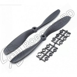
Length: 9″. Pitch: 4.7″. Weight: 20 gm. Shaft Diameter: 7.86 mm. Total Length: 9 inch / 225 mm. Material: ABS
Reference: RBD-0201
QUICK OVERVIEW Transmitter: FS-TH9X Upgrade with FS-RM003 2.4GHz Module Receiver: FS-IA10B Default Mode: Mode-2 Input Power: 12V DC (1.5V x 8 AAA Battery) Bidirectional System Frequencies-Hopping Omni-directional High Gain Antenna Low Power Consumption
Reference: RBD-0718
Model Type: Digital Radio Transceiver. Sensitivity: 1024. Bandwidth: 500 kHz. Default Operating Mode: Mode 2 (Left-Hand Throttle). No. of Channels: 6. Operating Voltage: 12V DC (1.5AA x 8 Battery) (not included).
Reference: RBD-0719
Bandwidth (KHz): 500. RF Range (GHz): 2.40 ~ 2.48. No. of channels: 6. Remote controller weight (gm): 400. Power: 6V (1.5V AA*4). Antenna Length: 26mm * 2 (dual antenna). Transmitting Power: ≤ 20dBm. RF Receiver Sensitivity: -105dbm. RoboticsBD
Reference: RBD-0729
Frequency (MHz) 1575 +/- 5 MHz Gain > 28 dBi (with LNA) Impedance (Ω) 50 Ω VSWR < 1.5 Polarization RHCP Power Handling (W) 50 watts Cable Length: 3Meter Connector: SMA-Male
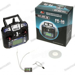
Reference: RBD-0957
Item name: FS-RX2A Radio receiver Channel: 10 RF Range: 2.408-2.475GHZ Number of bands: 135 RX Sensitivity: -92dBm 2.4GHz protocol: AFHDS 2A Signal output: IBUS, PPM Compatible Transmitter: All AFHDS 2A Transmitter, Ex.: FS-I6, FS-I6X, FS-I6S, FS-TM8, FS-TM10, FS-I10.
Reference: RBD-1023
Frequency (MHz) 1575 +/- 5 MHz Gain > 28 dBi (with LNA) Impedance (Ω) 50 Ω VSWR < 1.5 Polarization RHCP Power Handling (W) 50 watts Cable Length: 3Meter Connector: SMA-Male
Reference: RBD-0172
FlySky FS-T6 2.4ghz Digital Proportional 6 Channel Transmitter & Receiver System FlySky Introduces its newest 6 channel 2.4GHz system, The FS-T6. After years of success with the CT6B, FlySky presents the new FS-T6 with loads of cool and convenient features making the operation of this transmitter simple and instinctive.
Reference: RBD-2167
Skydroid 5.8G 150CH Full Channel UVC Dual Antenna Control Receiver OTG FPV Receiver Designed for Android phones with UVC support and OTG compatibility Dual antenna design for improved signal stability Channel waveform display and channel adjustment button added for convenience Supports audio playback through the app Automatic scanning mode activated by...
Radiolink AT9S Pro 10/12 Channels 2.4GHz RC Transmitter and Receiver Mode 2