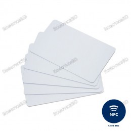
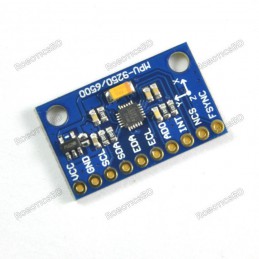
Contactless transmission of data and supply energy (no battery needed)
Operating distance: Up to 100mm (depending on antenna geometry) RoboticsBD
Operating frequency: 13.56MHz
Data transfer: 106 kbit/s
Data integrity: 16 Bit CRC, parity, bit coding bit counting
Anticollision
Typical ticketing transaction: <100 ms ( including backup management)...
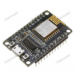
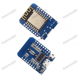
The ESP8266 Witty Cloud ESP-12F WiFi Module is a powerful WiFi enabled processor in a compact package that incorporates an RGB LED, LDR light sensor and pushbutton for easy stand-alone operation.
The ESP8266 Witty Cloud ESP-12F WiFi Module is a powerful WiFi enabled processor in a compact package that incorporates an RGB LED, LDR light sensor and pushbutton for easy stand-alone operation.
PACKAGE INCLUDES:
ESP8266 Witty Cloud ESP-12F WiFi Module
KEY FEATURES OF ESP8266 WITTY CLOUD ESP-12F WIFI MODULE:
Microcontroller: ESP-8266 32-bit
Clock Speed: 80 / 160MHz
USB Converter: CH340
USB Connector: Micro USB
Operating Voltage: 3.3V
Flash Memory: 4 MB
Digital I/O: 11
Analog Inputs: 1
Communications: Serial, SPI. I2C and 1-Wire via software libraries
WiFi: Built-in 802.11 b/g/n
LED: Built-in RGB LED
Light Sensor: Built-in LDR photoresistor
Buttons: Built-in pushbutton
Programming: Compatible with Arduino IDE and NodeMCU
Besides adding WiFi capability, the main claim to fame for the ESP8266 processor over the AVR processor of the standard Arduino is that it has a larger 4 MB of Flash memory and runs at clock speeds of 80 MHz and can sometimes optionally be overclocked to 160 MHz and therefore has a fast processing speed. These can be used as a stand-alone MCU in place of something like an Arduino or it can be used as a peripheral in conjunction with another MCU just to provide WiFi capability.
The module incorporates several common components including an RGB LED and LDR photoresistor which makes it more of a stand-alone device. It also incorporates a pushbutton for initiating an action of some type.
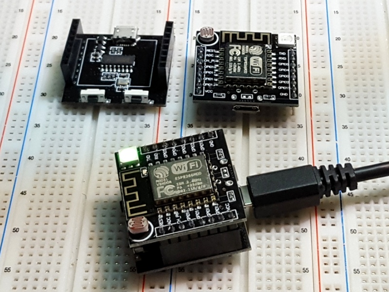
The module is constructed of two stacked boards. The top board is the main processor board with the ESP8266 and the bottom board provides the USB interface. If desired, once the module is programmed and if the USB is no longer required, the top board can be removed and used without the bottom board. Note that the USB connector on the top board can optionally provide power to the module if using it without the bottom board, but it does not provide USB communications.
Digital I/O
All of the Digital I/O support PWM and interrupts except pin 16 which does not support interrupts. In addition they can be configured to have pull-up or pull-down resistors. Though there are 11 digital I/O pins, 2 are typically reserved for use as the TX/RX lines if serial communications are used which leaves 9 digital I/O for other uses. Some of these 9 pins are connected to the on-board LEDs, but can also be used for other purposes if needed.
PWM range by default is 0-1023 rather than the typical 0-255 found on Arduino. The range can be modified using the command analogWriteRange (255) which sets the range between 0-255.
The PWM frequency is 1kHz by default. Similarly it can be modified using the analogWriteFreq(500) to set the frequency to 500 Hz as one example.
The pins are labeled GPIOx. When using with Arduino IDE, the digital pin number is the samethe pin number, so GPIO2 is referenced as just ‘2’.
The small blue on-board LED is connected to pin 2 (GPIO2).
The on-board general purpose pushbutton on the top board is connected to pin 4 (GPIO4).
The RGB LED is common cathode and so lights when driven HIGH. It is connected to the following pins:
Pin 15 (GPIO15) = RGB Red LED
Pin 12 (GPIO12) = RGB Green LED
Pin13 (GPIO13) = RGB Blue LED
Per spec, the digital I/O is limited to 3.3V, but the mfr has made statements that the digital pins are in fact 5V tolerant and there are many installations using the module directly connected to the logic lines of 5V MCUs, so use your own judgment.
Analog I/O
The analog input A0 (ADC) is a single 10-bit ADC input which is connected to the LDR (Light Dependent Resistor).
The LDR has a dark resistance of about 2.5K and is in series with a 470 ohm resistor to form a voltage divider that feeds the ADC input. The LDR is connected to the Vcc side of the voltage divider and the 470 ohm resistor connects to ground. As the light intensity increases, the LDR resistance decreases and therefore the voltage on the ADC input increases.
By measuring the voltage, the relative brightness of the light falling on the sensor can be determined.
Powering the Module
The module can be powered via the USB port on either the top or bottom board or by using an external 5V power supply connected to the Vcc pin.
The top module includes a 3.3V regulator which regulates the 5V down to the 3.3V required by the ESP8266.
Programming the Module
The board uses the CH340 chip on the bottom board for USB communications, so the bottom USB must be used for programming or communicating with the module.
If you have any issues with connecting to the board, you may need to download a driver for the CH340. Just search for Arduino CH340 driver and you will find a number of sources for drivers depending on what Windows or Mac operating system you are using.
The module comes preloaded with the NodeMCU software that accepts the standard AT command set.
It also can be programmed in C using the Arduino IDE and is how the modules are most often used. An example program is shown down below. If a program is download via the IDE, it will overwrite the NodeMCU software or whatever else was loaded before. If that is a problem for what you want to do, the NodeMCU software can always be reloaded.
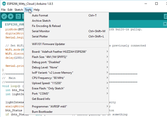
There are many instructions for installing and using ESP8266 based boards with the Arduino IDE, but here is a short-hand version. Note that once the ESP8266 board type is added to the IDE, there will be many more items added to the Tools drop down menu.
Open Preferences window and enter the following into the ‘Additional Board Manager URLs’ field: “http://arduino.esp8266.com/stable/package_esp8266com_index.json“.
Under Boards Manager, install ESP8266 by ESP8266 Community.
Under Tools/Boards select “Adafruit Feather HUZZAH ESP8266“.
Set Upload Speed to “115200“.
Select the port that the board is attached to. In my case it happened to be COM3
In the Serial Monitor window, set comm rate to 115200 and line ending to Both NL & CR
Here is what it looks like on my setup.
To test whether the board is basically working and you can communicate with it using the preloaded NodeMCU software, you can open a Serial Monitor Window and simply enter ‘AT‘ into the serial monitor top window and hit ENTER. The board should return with ‘OK‘. That indicates the board is alive and the setup is working.
If you don’t get the OK:
Ensure that you have the USB cable plugged into the bottom USB connector, not the top.
Make sure that you have the correct Comm Port selected.
Verify the serial monitor window is set to a baud rate of 115200 and the line ending is set to Both NL & CR.
Our Evaluation Results:
These modules have good overall build quality.
Things to Watch Out For
The micro USB connector has a very small footprint and solder pads which makes it popular for small MCUs where space is limited. As with any MCU that uses the micro USB connector, some care should be taken not to put excessive strain on the USB cable or it is possible for the connector to be dislodged from the board.
The Witty Cloud (and ESP8266 processors in general ) have a couple of software quirks to be aware of compared to working with a standard Arduino.
First is that the compile and download time when using the IDE tends to be longer than for typical Arduino boards. This is especially true the first time a program is compiled or if the build options are changed which require a complete recompile. Subsequent compiles do run faster.
The second thing is that the module does not like long delays in code and it may cause the module to do a watchdog software reset. This is because the module has a network stack to handle the WiFi and that needs to be serviced regularly by the processor. An example of what not to do would be using something like a tight DO/WHILE loop waiting for a button to be pressed.
For instance in the example program down below, if you were to check the button using code like this which blocks the program until the button is pushed, you will run into this problem as it does not allow any free time for the processor to go off and reset the watchdog timer on occasion, so it thinks it has locked up and resets itself.
Do {
btn_Status =digitalRead (BUTTON_PIN)
} while (btn_Status==HIGH)
If the module keeps resetting every couple of seconds, look for this blocking type of issue in your code. This can be resolved by inserting the yield() function into the loop as that function lets the processor go off and take care of other business before returning to the loop.
Using the delay() function does not create the same blocking issue because the delay() function internally calls the yield() function every so often.
Example Setup
The program below is based on one of the sample programs ‘WiFiScan’ that is available once the ESP8266 boards are loaded into the IDE. It sends the list of networks found to the Serial Monitor window.
The version here uses the built-in pushbutton to initiate the scan for any available WiFi networks and turns on the on-board LED while a scan is in process. It also monitors the light level on the LDR and adjusts the brightness of the RGB green LED based on the amount of light that the LDR sensor is detecting. If you put your finger on the LDR, the RGB LED should go out.
The only connection that needs to be made is the USB cable to the USB connector on the bottom board. Ensure HUZZAH ESP8266 is selected as the board type in the IDE and the correct COM port is selected. Once the program is downloaded, open the Serial Monitor window and ensure that the baud rate is set to 115200. Once you press the pushbutton on the edge of the top board, a scan of the available WiFi networks will be displayed.
ESP8266 Witty Cloud ESP-12F WiFI Module Example Program
/* This sketch demonstrates how to scan for available WiFi networks.
A button input is used to initiate the scan and the on-board LED
is lit to indicate when a scan is in process
On each loop, also check the analog input connected to the LDR and adjust
the brightness of the RGB Green LED to match the measured brightness.*/#include"ESP8266WiFi.h"constintBUTTON_PIN=4;// Define pin the button is connected toconstintON_BOARD_LED=2;// Define pin the on-board LED is connected toconstintRGB_G_PIN=12;// RGB Green LEDconstintLDR_PIN=A0;// Define the analog pin the LDR is connected to//===============================================================================// Initialization//===============================================================================voidsetup(){pinMode(ON_BOARD_LED,OUTPUT);// Initialize the LED_BUILTIN pin as an outputpinMode(BUTTON_PIN,INPUT_PULLUP);// Initialize button pin with built-in pullup.digitalWrite(ON_BOARD_LED,HIGH);// Ensure LED is offSerial.begin(115200);// Set comm rate to 115200// Set WiFi to station mode and disconnect from an AP if it was previously connectedWiFi.mode(WIFI_STA);WiFi.disconnect();delay(100);Serial.println("Setup done");}//===============================================================================// Main//===============================================================================voidloop(){intbtn_Status=HIGH;intlightIntensity;lightIntensity=analogRead(LDR_PIN);// Read the light intensityanalogWrite(RGB_G_PIN,map(lightIntensity, 40,1023,0, 1023));btn_Status=digitalRead(BUTTON_PIN);// Check status of buttonif(btn_Status==LOW){// Button pushed, so do somethingSerial.print("Light Intensity Reading: ");Serial.println(lightIntensity);Serial.println("scan start");digitalWrite(ON_BOARD_LED,LOW);// Turn LED ON// WiFi.scanNetworks will return the number of networks foundintn=WiFi.scanNetworks();Serial.println("scan done");if(n==0)Serial.println("no networks found");else{Serial.print(n);Serial.println(" networks found");for(inti=0;i<n;++i){// Print SSID and RSSI for each network foundSerial.print(i+1);Serial.print(": ");Serial.print(WiFi.SSID(i));Serial.print(" (");Serial.print(WiFi.RSSI(i));Serial.print(")");Serial.println((WiFi.encryptionType(i)==ENC_TYPE_NONE)?" : Unsecure":" : Encrypted");delay(10);}}Serial.println("");digitalWrite(ON_BOARD_LED,HIGH);// Turn LED Off}}
Before they are shipped, these modules are:
Sample inspected and tested per incoming shipment.
Notes:
None
Technical Specifications
Microcontroller
ESP8266 Tensilica 32-bit
Serial to USB Converter
CH340
Operating Voltage
3.3V
Input Voltage
5
Digital I/O Pins
11
PWM I/O Pins (Shared with Digital I/O)
10
Analog Input Pins
1 (10-bit) Max input 3.2V
DC Current per I/O Pin
12mA (Max)
Hardware Serial Ports
1
Flash Memory
4 MBytes
Instruction RAM
64 KBytes
Data RAM
96 KBytes
Clock Speed
80MHz
Network
IEEE 802.11 b/g/n WiF
Built-in LED
Attached to pin 2
RGB LED
R = Pin 15, G = Pin 12, B = Pin 13
General Purpose Pushbutton
Attached to pin 4
USB Connector Style
Micro-B Female
Board Dimensions (L x W x H)
32 x 32 x 17 mm (1.3 x 1.3 x 0.7″)
Country of Origin
China
What is the price of ESP8266 Witty Cloud ESP-12F WiFi Module in Bangladesh?
The latest price of ESP8266 Witty Cloud ESP-12F WiFi Module in Bangladesh is BDT 490 You can buy the ESP8266 Witty Cloud ESP-12F WiFi Module at best price from our RoboticsBD or visit RoboticsBD Office.
Please note that the product information provided on our website may not be entirely accurate as it is collected from various sources on the web. While we strive to provide the most up-to-date information possible, we cannot guarantee its accuracy. We recommend that you always read the product labels, warnings, and directions before using any product.
Product Images are shown for illustrative purposes only and may differ from the actual product.
Product Details
RBD-3261
27 Items
All product reviews are from verified purchases and are comply with DIRECTIVE (EU) 2019/2161
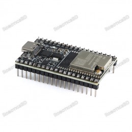
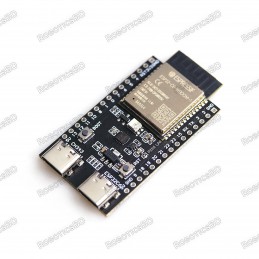
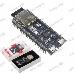
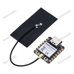
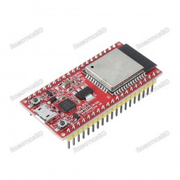
The ESP32-WROOM-32U Development Board with USB Type-C is a compact and feature-rich board powered by the ESP32-WROOM-32U module from Espressif. This version includes a CP2102 USB-to-Serial converter and supports an external antenna via the onboard U.FL connector, allowing for improved wireless performance in demanding environments. Ideal for IoT, wireless...
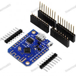
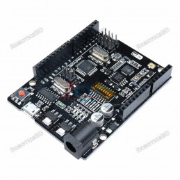
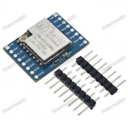
D1 Mini board with 4 MB flash memory and ESP8266 chipset. The board can be programmed with Arduino IDE, has the CH340 USB chipset and allows you to create IoT devices quickly and easily.
Arduino compatibility
Full integration
USB-TTL converter
32 Mb flash memory
Dual microcontrollersA high-quality USB cable is essential for this board to ensure sufficient current supply; otherwise, your board may not be recognized by the Windows Device Manager. Please avoid using mobile phone cables and instead use the recommended cable available here:...
100% brand new and high quality.
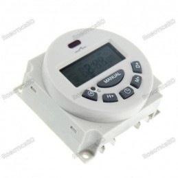
Widely used in street lights, neon lights, bells, radio and television equipment, production equipment, electrical equipment and household appliances automatic control.
Built-in high-performance batteries as backup power in case of no electricity can still maintain time display and storage of.
Auto timer error correction....
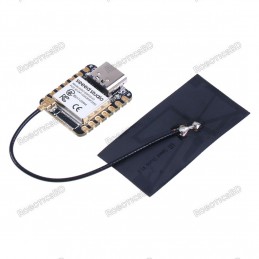
Wi-Fi + Bluetooth LE MCU Module with complete wireless functionality for versatile IoT applications.
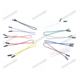
Pin headers for easy interfacing; ideal jumper wire connections.
USB-to-UART bridge for power supply, programming, and communication with speeds up to 3 Mbps.
Neural network acceleration and signal processing support for advanced workloads.
RGB LED and...
The Seeed Studio XIAO ESP32-C3 is a powerful and ultra-compact microcontroller board built around the 32-bit RISC-V-based ESP32-C3 SoC. It offers robust wireless connectivity via 2.4GHz Wi-Fi and Bluetooth 5.0, making it an excellent solution for IoT, smart home, and wearable device applications. With support for Arduino and CircuitPython, deep sleep...
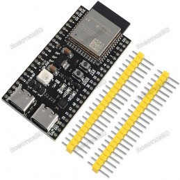
ESP32-S3-WROOM-1-N16R8(16M Flash/8SRAM)
Powerful ESP32-S3 chip for enhanced processing capabilities
Dual Type-C USB ports for easy connectivity
Built-in Wi-Fi and Bluetooth for seamless communication
16MB flash memory for ample storage space
8MB PSRAM for efficient multitasking
Micropython support for easy programming
Ideal for IoT projects, robotics, and...
The Seeed Studio XIAO ESP32-S3 is a powerful, thumb-sized microcontroller development board built around the ESP32-S3 dual-core Xtensa LX7 processor. Running at up to 240MHz, this board delivers high performance while maintaining exceptional energy efficiency. Supporting both 2.4GHz WiFi and Bluetooth 5.0 (BLE), it is ideal for a broad range of wireless...
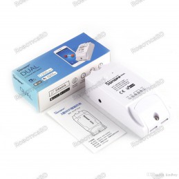
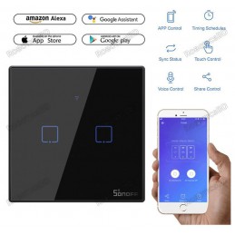
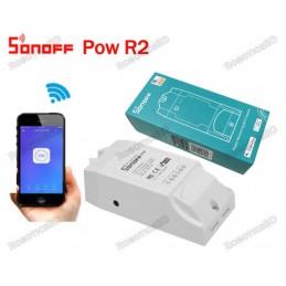
Can control up to 2 device
220V Model : T3EU2C
Remotely control devices through a phone
Turn on/off devices with Amazon Alexa and Google Assistant
Touch control buttons for convenient operation
Set a particular time to turn on/off devices
Customize one or groups of SONOFF devices to turn on/off with a simple tap
Allow you to manage devices when there is...
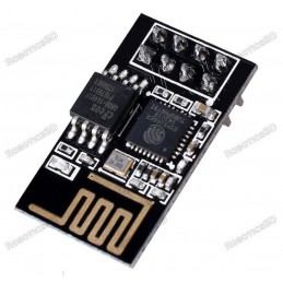
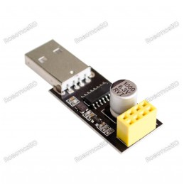
The ESP8266 ESP-01S is a compact, versatile Wi-Fi transceiver module designed to add wireless connectivity to microcontroller projects. Based on the ESP8266 chipset, it provides a cost-effective and reliable solution for IoT (Internet of Things) applications. The module features an integrated TCP/IP protocol stack, making it a complete Wi-Fi network...
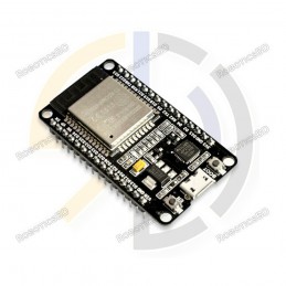
Integrated Wi-Fi and Bluetooth connectivity make this board a great choice for IoT projects and robotics.
The ESP32 chip on the board is a dual-core microcontroller that operates at up to 240 MHz, providing ample processing power for complex projects.
With 520 KB of SRAM and 4 MB of flash memory, the board has plenty of memory for storing and running...
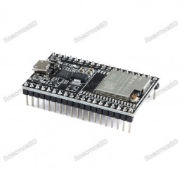
The ESP32-WROOM-32U Development Board with Micro USB is a versatile, compact solution ideal for developers looking to leverage the full power of the ESP32 in a breadboard-friendly format. With a CP2102 USB-to-Serial chip and support for external antennas via the U.FL connector, this board is well-suited for wireless communication, IoT projects, and remote...
Voltage range: 100-240V AC
Color: White
Remote Control
Monitor Energy Usage
Historical Energy Consumption
Overload Protection
Measure Power Usage for a Period
Sync Status
Timing Function
Share Control
Smart Scene
APP Supported
Check out New Product
Sonoff POWR320D Elite Smart Power Meter Switch
ESP8285 ESP-M2 Development Board with built-in 1MB FLASH memory
Features the reliable ESP8266 processor with full WiFi functionality
Pre-programmed with NodeMCU Lua firmware for quick project setup
Compact, solder-friendly design with onboard PCB antenna
Ideal for smart home automation, IoT projects, and sensor networks
Flash LED off: 180mA @ 5V.
Flash LED on to maximum brightness: 310mA @ 5V.
Deep-sleep: 6mA @ 5V min.
Modem-sleep: 20mA @ 5V min.
Light-sleep: 6.7mA @ 5V min.
Programmer: ESP32-CAM-MB MICRO USB Download Module
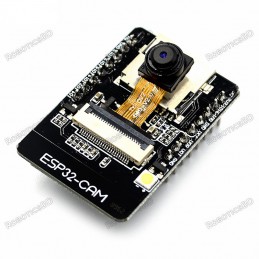
The ESP32 CAM does not come pre-assembled with the camera. You'll need to connect the camera ribbon cable to the board, a task which can be...
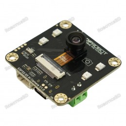
An intelligent camera module featuring advanced AI, voice interaction, and night vision capabilities. Ideal for IoT applications like surveillance and smart assistants.
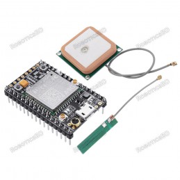
Quad-band 850/900/1800/1900MHz
Inner MT3337 GPS receiver, -165dBm precision, control on a same serial port.
Earphone/ microphone outputs on a card or external 32-ohm speaker + supports voice calls with an electret microphone.
Sending and receiving SMS.
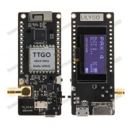
LILYGO TTGO
Model: 915MHZ CH9102F T3_V1.6.1
LoRa32 V2.1_1.6 Version 915Mhz or 433Mhz
ESP32 LoRa
OLED 0.96 Inch
SD Card
Bluetooth
WIFI
Wireless Module
ESP-32 SMA
This module is intended for advanced users who require moderate knowledge of GSM systems and microcontrollers. It needs wiring and firmware updates to unlock the country lock.
Dual-Band 900/ 1800 MHz
GPRS multi-slot class 10/8GPRS mobile station class B
Compliant to GSM phase 2/2+
Dimensions: 24*24*3 mm
Weight: 3.4g
Control via AT commands (GSM 07.07...
Powered by TSMC's 40nm technology for reliable and power-efficient performance.
Supports multiple I/O connections with 2.54mm pin headers for easy peripheral integration.
Equipped with CP2102-GM USB to Serial chip for smooth programming and debugging.
Compact, durable design with versatile applications in IoT, automation, and robotics.
Driver Chip: CH340G
Supports all basic windows versions.
The adapter plate integrated 1000μF solid capacitors to ensure the current supply
The power supply will not be a problem to make WIFI module crashes unresponsive.
Using 3225 SMD crystal oscillator, improve the stability of serial work, on a beautiful and tall.
Working voltage: 4.5V – 5.5V (Onboard...
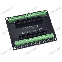
The ESP32-S Screw Terminal Adapter is a convenient breakout board designed to mount 38-pin ESP32-S development boards, making it easy to interface with external wiring. It features screw terminals and female headers for each pin, providing a secure and organized wiring solution for projects that require multiple external connections.
This adapter...
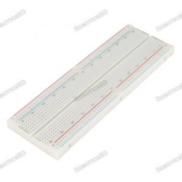
830 Solder-less Points
Ideal for Experimenting With Circuit Design In Labs
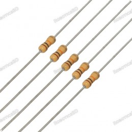
Compatible with resistance, diodes, transistors, LED’s, Capacitors and other types of electronic components
Colored coordinates for easy components placement.
Accept a variety of wire sizes 20-29 AWG
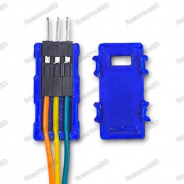
Tidy up your workspace and organize your jumper wires with this handy 3D printed housing for Dupont connectors.
Securely holds up to 3 jumper wires (3-pin) for easy access and strain relief.
No soldering required - simply snap the connector housings into place.
Compatible with Arduino, Raspberry Pi, sensors, LED strips, and various DIY electronics projects.
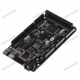
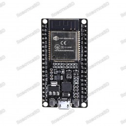
38 Pin version
2.4GHz Dual-Mode WiFi + Bluetooth Development Board, 38PIN
Ultra-Low power consumption works perfectly with the IDE
A high-quality USB cable is essential for this board to ensure sufficient current supply; otherwise, your board may not be recognized by the Windows Device Manager. Please avoid using mobile phone cables and instead use the...
Firstly, In terms of pins, the D1 Mini and NodeMCU V3 development boards are quite similar. They both break out all ESP8266 ESP-12E/F pins. The NodeMCU V3 board has additional 3V3 and GND pins. Hence, it is more suitable for various connections to devices with an additional button for the flash.
A high-quality USB cable is essential for this board to...
Communication distance: 15KM
Sensitivity: down to -148dBm
Programmable bit rates: up to 300kbps
RSSI dynamic range: 127dB
Wireless frequency: 433MHz
Working voltage: 1.8-3.7v
Working temperature: -40-+80 ℃The range depends on your antenna. If you need a longer range, you need to use a powerful antenna. (Antenna is not included)
The ESP8266 Witty Cloud ESP-12F WiFi Module is a powerful WiFi enabled processor in a compact package that incorporates an RGB LED, LDR light sensor and pushbutton for easy stand-alone operation.