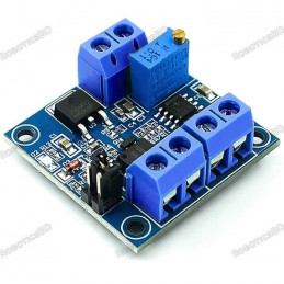
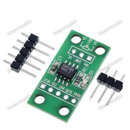
Reference: RBD-1354
Jumper Wire Single 20cm
Length: 8 inches/20 CM (Long) Material: Copper Plated Pin Spacing: 2.54mm.
Reference: RBD-1354
Length: 8 inches/20 CM (Long) Material: Copper Plated Pin Spacing: 2.54mm.
Reference: RBD-0351
Contactless transmission of data and supply energy (no battery needed) Operating distance: Up to 100mm (depending on antenna geometry) RoboticsBD Operating frequency: 13.56MHz Data transfer: 106 kbit/s Data integrity: 16 Bit CRC, parity, bit coding bit counting Anticollision Typical ticketing transaction: <100 ms ( including backup management)...
Reference: 0245
Choose your desire Resistor value from below:
Reference: 0031
3 Types Available (Please select from option) 1. Male to Male 2. Male to Female 3. Female-Female
Reference: RBD-0768
Size: 5mm Color: RED Head Shape: Round Lens Appearance: Transparent
Reference: 1353
Length: 12.5 inches/30 CM (Long) Material: Copper Plated Pin Spacing: 2.54mm.
Reference: RBD-0761
Breadboard friendly Mounting Style: Through Hole Mounting Direction: Vertical
Bi-directional mux can handle analog and digital signals.
The 16-Ch Analog / Digital Mux Module mounts a 74HC4067, a 16-channel multiplexer/demultiplexer IC that can route both analog and digital signals in both directions.
1 of 16 input channels can be routed to 1 output or 1 input can be routed to 1 of 16 output channels. It can handle analog signals such as from analog sensors or a bank of potentiometers or it can handle digital signals such as from switches, digital sensors or even serial communications.
The 74HC4067 can operate over the range of 2 to 6V, so it is compatible with both 3.3 and 5V logic.
Four address lines (S0-S3) select one of the 16 channels and connects it to the input/output pin (SIG). It uses binary addressing, so address 0000 is Channel 0, address 1111 is Channel 15. When a channel is ON, it has a resistance of about 70 ohms which allows signals to flow both ways. With a 5V power supply, we measured about 60 ohms. Maximum current is 25mA through any of the channels.
There is an enable pin (EN) that is active LOW and defaults to that value. When LOW, the device enables the channel selected by the address lines. If EN is pulled HIGH, all channels are disabled.
On the electronics module there are 2 rows of breakout points. These can be used to connect wires or header pins can be soldered in depending on the application.
1×8 Header
1×16 Header
This is one of those devices that sounds complicated, but is actually easy to use. When using this device, it is perhaps easiest to think of it as a bank of 16 mechanical switches with one side of all the switches tied together with a built-in series resistor of 60-70 ohms that goes to a microcontroller analog or digital pin. The other side of the switches connect to analog or digital signals that you want to monitor or control. The main rule is that only one switch can be turned on at a time.
Since only one output can be active at a time these devices are generally most useful for sequentially reading multiple inputs rather than controlling outputs.
The board comes with male header pins. Whenever soldering header pins of this type, it is always recommended to insert the pins into a solderless breadboard while the module is being soldered to ensure the pins stay aligned with the breadboard spacing.
The example program below demonstrates some of its capability. It sets the device up on the A0 analog input pin and scans the 16 channels and prints out the analog value which will range from 0 to 1023. If the inputs are left floating, the readings will be random. If a pin is pulled low, it should read close to 0. If it is pulled to Vcc, it should read close to 1023.
/* 74HC4067 Analog / Digital Mux Example This is setup to read 1 of 16 analog inputs such as from analog sensors which is the most common use of this device. The SIG pin can be connected to a digital pin if it is desired to work with digital data instead of analog. Accessing the device uses a table and small function to translate from channel 0-15 to the binary address to make life a little easier */ // Define pins used below #define S0_PIN 4 // Use any 4 available digital pins for addressing the 74HC4067 #define S1_PIN 5 #define S2_PIN 6 #define S3_PIN 7 #define SIG_PIN A0 // Use any available analog pin. // Table below is used to translate from 0-15 to binary address of device. int channel_address_table[16][4] = { // s0, s1, s2, s3 channel {0, 0, 0, 0}, // 0 {1, 0, 0, 0}, // 1 {0, 1, 0, 0}, // 2 {1, 1, 0, 0}, // 3 {0, 0, 1, 0}, // 4 {1, 0, 1, 0}, // 5 {0, 1, 1, 0}, // 6 {1, 1, 1, 0}, // 7 {0, 0, 0, 1}, // 8 {1, 0, 0, 1}, // 9 {0, 1, 0, 1}, // 10 {1, 1, 0, 1}, // 11 {0, 0, 1, 1}, // 12 {1, 0, 1, 1}, // 13 {0, 1, 1, 1}, // 14 {1, 1, 1, 1} // 15 }; //=============================================================================== // Initialization //=============================================================================== void setup() { pinMode(S0_PIN, OUTPUT); // Set addressing pins as outputs pinMode(S1_PIN, OUTPUT); pinMode(S2_PIN, OUTPUT); pinMode(S3_PIN, OUTPUT); Serial.begin(9600); // Set Serial Monitor window comm speed } //=============================================================================== // Main //=============================================================================== void loop() { int mux_Value; // Step through each much channel and report what we are seeing for (int i=0; i<16; i++){ Mux_Addr (i); delay(1000); // Slow things down for readability and allow address to settle mux_Value = analogRead(SIG_PIN); // Read analog value from mux Serial.print("Ch"); Serial.print(i); Serial.print(": "); Serial.println(mux_Value); //delay(1000); // Delay 1 second to slow everything down for readability } Serial.println(); delay(3000); // Read the mux channels every 3 seconds } // Function to update the mux binary address bits given the channel number 0-15 void Mux_Addr (int ch_Addr) { digitalWrite(S0_PIN, channel_address_table[ch_Addr][0]); digitalWrite(S1_PIN, channel_address_table[ch_Addr][1]); digitalWrite(S2_PIN, channel_address_table[ch_Addr][2]); digitalWrite(S3_PIN, channel_address_table[ch_Addr][3]); }
The latest price of 74HC4067 16-Ch Analog / Digital Mux Module in Bangladesh is BDT 250 You can buy the 74HC4067 16-Ch Analog / Digital Mux Module at best price from our RoboticsBD or visit RoboticsBD Office.
Please note that the product information provided on our website may not be entirely accurate as it is collected from various sources on the web. While we strive to provide the most up-to-date information possible, we cannot guarantee its accuracy. We recommend that you always read the product labels, warnings, and directions before using any product. |
Product Images are shown for illustrative purposes only and may differ from the actual product. |
Reference: RBD-3206
The Metal Motor Servo Tester ESC Checker Master is a professional-grade tool designed to test and calibrate servos and electronic speed controllers (ESCs) for RC drones, cars, boats, and helicopters. With its durable aluminum alloy construction and versatile functionality, this tester allows you to adjust and synchronize multiple servos or ESCs with ease....
Reference: RBD-2054
Multi-functional transistor tester. Automatic detection of NPN and PNP transistors, FET, diodes, dual diode, thyristor and SCR. Automatic identification of the transistor pinout. Can be used as a Square signal generator. Can be used as a PWM signal generator.
Reference: RBD-3166
The GY-SI5351 Clock Signal Generator Module is a versatile and precise clock generation device, capable of producing multiple independent frequencies with minimal error. Controlled via I2C, this module is perfect for applications requiring precise frequency synthesis for audio, video, communication, and general electronic projects. With three independent...
Reference: RBD-1923
Conversion range: 0% -100% PWM to 0-10v voltage PWM signal reception frequency range: 1KHz – 3KHz Operating voltage: 12V – 30V DC Allowable error: 5%
Reference: RBD-2676
Suitable for use with a wide range of stepper motors and drivers. Can be integrated into a simple control platform with a stepper motor and DC power supply. Offers three selectable low-frequency signal options: high (5.4k-160kHz), middle (540-16.6kHz), and low (80-2.4kHz), adjustable via jumper settings. Capable of producing both pulse and PWM signals,...
Reference: RBD-0410
Supply voltage: 6V-15V Chip: X9C103S Dimensions : 28 x 14 x 4 (LxWxH) mm. RoboticsBD 10K span potentiometer. Potentiometer center tap between the 0-10k slide in total 100 (potentiometer wiper typical impedance 40 ohms)
Reference: RBD-3122
The CJMCU-608 ATECC608A module is a high-security cryptographic memory module designed to store and manage cryptographic keys. Equipped with a random number generator (RNG), this module supports various security functions, including signature generation, encryption, and decryption. It is ideal for applications that require secure key management and data...
Reference: RBD-1834
PT100 to 0-5V Converter Voltage Signal Conditioner PCB-mounted
Reference: RBD-2354
Versatile Signal Generator: Supports dual modes (PWM and PULSE) for enhanced flexibility. Wide Frequency Range: Operates from 1Hz to 150KHz with ±2% frequency accuracy. Customizable Outputs: Adjust duty cycle, pulse width, delay, and number of pulses. User-Friendly Interface: LCD display for real-time monitoring and precise adjustments. Compact &...
Reference: RBD-2761
ICL8038 12V to 15V, Signal Generator, Medium/Low Signal, Frequency 10Hz-450KHz, Triangular/Rectangular/Sine Wave Generator, Module Working voltage: 12V ~ 15V Output: Triangular wave, Square wave and sine wave. Frequency range: 10HZ ~ 450kHz Low distortion sine wave: 1% Duty cycle range: 2% to 98% Low temperature drift: 50ppm / ℃ Triangular wave output...
Reference: RBD-2230
Main chip: NE555 Input Voltage: 5V-15V DC. Generate an adjustable pulse for MCU. Generate an adjustable pulse, to control circuitry associated.
Reference: RBD-2207
2 sine wave and 2 square wave output. AD9850: 0-40MHz. After the 20-30MHz frequency harmonics increases, the waveform will be less and less clean. Low-pass filter with 70MHz, so the waveform better than SN. Parallel and serial data input can be selected via a jumper.
Reference: RBD-2554
Type: Operational Amplifier Test Board Material: PCB Size: Approx. 92 x 57 x 17mm / 3.62 x 2.24 x 0.67in Working Voltage: DC 12V Working Current: >100mACompatible Op-Amp Models: Single Op-Amp: LM741, LF356, NE5534, TL071, TL081, OP07, and other standard package single op-amps. Dual Operational: LM358, NE5532, TL072, TL082, MC1458, RC4558, OP275, AD827,...
Reference: RBD-3305
The TL494 PWM Adjustable Pulse Generator Module is a versatile and efficient pulse width modulation (PWM) signal generator, capable of producing a 5V PWM signal ranging from 500Hz to 100kHz. With its adjustable frequency and duty cycle, this module provides precise control over pulse generation, making it ideal for various applications including power...
Reference: RBD-3320
The LM358 Duty and Frequency Adjustable Square Wave Signal Generator is a compact and versatile module designed for pulse signal generation, motor control, microcontroller triggering, and circuit testing. Featuring an adjustable duty cycle and frequency, this module provides users with a fine-tuned square wave output for various applications.
Reference: RBD-2340
2-channel PWM pulse frequency and duty cycle adjustable signal generator module Generates square and rectangular waveforms for experiment and development Frequency range: 1Hz to 150KHz, adjustable in three precision levels Features serial port control with customizable PWM settings via commands Compact design (44x30x11mm) with 5–30V DC operating voltage
Reference: RBD-2467
0-150kHz PWM generator in a panel mount enclosure
Reference: RBD-2357
Compact PWM signal monitor for accurate pulse width and frequency measurement. Wide range detection: Supports pulse widths from 50-9950us. Ideal for testing receivers, flight controllers, and servos. Displays clear signal status with anti-reverse connection protection. Upgraded design: Smaller, better performance, and quick display updates. Lightweight...
Reference: RBD-1576
High-Precision Wave Generator. Comes without Soldered. Can Generate Waveforms from 1Hz to 1MHz. Has Frequency and Amplitude Adjustment Feature. Frequency Adjustment Supports Corse and Fine Adjustment.The current stock is unassembled and requires soldering.
Reference: RBD-0756
Very low supply current Photo-detector and preamplifier in one package Internal filter for PCM frequency Improved shielding against EMI Supply voltage: 2.5 V to 5.5 V Improved immunity against ambient light
Reference: RBD-1000
Adjustable Voltage Regulator Power Management IC
Reference: RBD-2027
5.08mm pitch. Pin header: Tin plated brass. Contacts: Nickel plated brass. Strong, compact, lightweight. Heat resistant.
Reference: RBD-2769
Model MP3-TF-16P / FN-M16P To Connect with Arduino easily use the adapter board: Mini MP3 Easy Connector Board for Mini MP3 Module
Reference: RBD-1010
Timing from microseconds to hours A stable or monostable operation Adjustable duty cycle TTL compatible output can sink or source up to 200mA