
Product Images are shown for illustrative purposes only and may differ from the actual product.


 Store Pickup Available!
 Free Ship Over 5000 BDT
 Quality Product
 No Warranty
 No Replacement
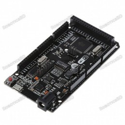
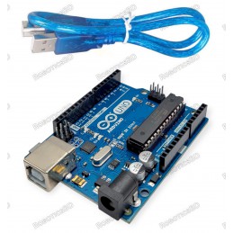
The ATmel MCU ATMEGA16U2 MEGA 2560 R3 Improved Version CH340G Board is a micro-controller board base on the ATmega2560. It has a USB host interface to connect with Android based phones, base on the MAX3421e IC. RoboticsBD
It has 54 digital input/output pins (of which 15 can be used as PWM outputs); 16 analog inputs, 4 UARTs (hardware serial ports), a 16 MHz crystal oscillator; a USB connection, a power jack, an ICSP header, and a reset button. The MEGA ADK is base on the Mega 2560. Similar to the Mega 2560 and Uno, it features an ATmega8U2 program as a USB-to-serial converter. Revision 3 of the Mega ADK board has a resistor pulling the 8U2 HWB line to ground, making it easier to put into DFU(Device Firmware Upgrade) mode. RoboticsBD
The board has the following new features:
The Mega Arduino R3 Android Accessory Development Kit (ADK) can be power via the USB connection or with an external power supply. The power source is select automatically. External (non-USB) power can come either from an AC-to-DC adapter (wall-wart) or battery. The adapter can be connected by plugging a 2.1mm center-positive plug into the board’s power jack. RoboticsBD
Leads from a battery can be inserted in the GND and Vin pin headers of the POWER connector. Because the Mega R3 Android Accessory Development Kit (ADK) is a USB Host, the phone will attempt to draw power from it when it needs to charge. When the ADK is power over USB, 500mA total is available for the phone and board.
Because Atmel is moving more and more of their production capacity to surface mount ICs, the DIP packaged ATmega is becoming more and more difficult to get. The board is identical to the PTH version of the Uno, but you won't be able to remove the ATmega without some hot-air. This change shouldn't affect most users. Besides - when was the last time you managed to destroy an ATmega and needed to repair an Arduino board? Those things are nearly indestructible. Featured By RoboticsBD.
Product Images are shown for illustrative purposes only and may differ from the actual product.
RoboticsBD RoboticsBD RoboticsBD RoboticsBD RoboticsBD RoboticsBD RoboticsBD RoboticsBD RoboticsBD RoboticsBD
*Please note that the boards have a CH340G USB-Controller rather than ATmega16 like regular MEGA2560. They are recognized on Linux without any additional drivers. Mac OS and Windows users may need to install an additional driver. RoboticsBD
RoboticsBD RoboticsBD RoboticsBD RoboticsBD RoboticsBD RoboticsBD RoboticsBD RoboticsBD RoboticsBD RoboticsBD
| General Specification | |
| Input Voltage (recommended) | 7-12V |
| Digital I/O Pins | 54 (of which 15 provide PWM output) |
| Analog Input Pins | 16 |
| Flash Memory | 256 KB of which 8 KB used by boot-loader. |
| Microcontroller | ATmega2560 |
| Country of Origin/Manufacture | China |
| PWM Output Pins | 14 |
| Dimensions (mm) LxWxH | 110 x 53 x 15 mm. |
| Weight (gm) | 35 |
| Shipment Weight | 0.037 kg |
| Shipment Dimensions | 10.5 × 5.5 × 1.5 cm |
Please allow 5% measuring deviation due to manual measurement.
RoboticsBD RoboticsBD RoboticsBD RoboticsBD RoboticsBD RoboticsBD RoboticsBD RoboticsBD RoboticsBD RoboticsBD
Memory
The Mega R3 Android Accessory Development Kit (ADK) has 256 KB of flash memory for storing code (of which 8 KB is used for the bootloader); 8 KB of SRAM and 4 KB of EEPROM (which can be read and written with the EEPROM library).
Input and Output
Each of the 50 digital pins on the Mega R3 Android Accessory Development Kit (ADK) can be used as an input or output; using pinMode(), digitalWrite(), and digitalRead() functions. They operate at 5 volts. Each pin can provide or receive a maximum of 40 mA . has an internal pull-up resistor (disconnect by default) of 20-50 kOhm. In addition, some pins have specialized functions:
MAX3421E
The Mega R3 Android Accessory Development Kit (ADK) has 16 analog inputs, each of which provides 10 bits of resolution (i.e. 1024 different values). By default, they measure from ground to 5 volts, though is it possible to change the upper end of their range using the AREF pin and analogReference() function. There are a couple of other pins on the board:
Communication
The Mega R3 Android Accessory Development Kit (ADK) has a number of facilities for communicating with a computer, another Arduino, or other micro-controllers. The ATmega2560 provides four hardware UARTs for TTL (5V) serial communication. An ATmega8U2 on the board channels one of these over USB and provides a virtual com port to software on the computer (Windows machines will need a .inf file, but OSX and Linux machines will recognize the board as a COM port automatically. The Arduino software includes a serial monitor which allows simple textual data to be sent to and from the board.
The RX and TX LEDs on the board will flash when data is being transmitted via the ATmega8U2/16U2 chip and USB connection to the computer (but not for serial communication on pins 0 and 1). A Software-serial library allows for serial communication on any of the MEGA ADK’s digital pins. The ATmega2560 also supports TWI and SPI communication. The Arduino software includes a Wire library to simplify the use of the TWI bus, see the Wire library for details. For SPI communication, use the SPI library.
The USB host interface given by MAX3421E IC allows the Arduino MEGA ADK to connect and interact to any type of device that has a USB port. For example, allows you to interact with many types of phones, controlling Canon cameras, interfacing with keyboard, mouse and games controllers as Wiimote and PS3.
Programming
The Mega R3 Android Accessory Development Kit (ADK) can be the program with the Arduino software (download). For details, see the reference and tutorials. The ATmega2560 on the MEGA ADK comes preburn with a boot-loader (the same on Mega 2560) that allows you to upload new code to it without the use of an external hardware programmer. It communicates using the original STK500v2 protocol (reference, C header files).
You can also bypass the bootloader and program the microcontroller through the ICSP (In-Circuit Serial Programming) header using Arduino ISP or similar; see these instructions for details. The ATmega8U2 firmware source code is available in the Arduino repository. The ATmega8U2 is load with a DFU bootloader, which can be activated by:
Automatic (Software) Reset
Rather then requiring a physical press of the reset button before an upload, the Arduino MEGA ADK is designed in a way that allows it to be reset by software running on a connected computer. One of the hardware flow control lines (DTR) of the ATmega8U2 is connected to the reset line of the ATmega2560 via a 100 nano-farad capacitor. When this line is asserted (taken low), the reset line drops long enough to reset the chip. The Arduino software uses this capability to allow you to upload code by simply pressing the upload button in the Arduino environment.
This means that the boot-loader can have a shorter timeout, as the lowering of DTR can be well-coordinated with the start of the upload. This setup has other implications. When the MEGA ADK is connected to either a computer running Mac OS X or Linux, it resets each time a connection is made to it from software (via USB). For the following half-second or so, the bootloader is running on the MEGA ADK. While it is programmed to ignore malformed data (i.e. anything besides an upload of new code), it will intercept the first few bytes of data sent to the board after a connection is open.
If a sketch running on the board receives one-time configuration or other data when it first starts; make sure that the software with which it communicates waits for a second after opening the connection and before sending this data. The MEGA ADK contains a trace that can be cut to disable the auto-reset. The pads on either side of the trace can be solder together to re-enable it. It’s the label “RESET-EN”. You may also be able to disable the auto-reset by connecting a 110-ohm resistor from 5V to the reset line; see this forum thread for details.
USB Over-current Protection
The Mega R3 Android Accessory Development Kit (ADK) has a resettable polyfuse that protects your computer’s USB ports from shorts and overcurrent. Although most computers provide their own internal protection, the fuse provides an extra layer of protection. If more than 500 mA is applied to the USB port. The fuse will automatically break the connection until the short or overload is removed.
Physical Characteristics and Shield Compatibility
The maximum length and width of the Mega R3 Android Accessory Development Kit (ADK) PCB are 4 and 2.1 inches respectively; with the USB connector and power jack extending beyond the former dimension. Three screw holes allow the board to be attached to a surface or case. Note that the distance between digital pins 7 and 8 is 160 mil (0.16″); not an even multiple of the 100 mil spacing of the other pins. The MEGA ADK is designed to be compatible with most shields design for the Uno, Diecimila or Duemilanove.
Digital pins 0 to 13 (and the adjacent AREF and GND pins), analog inputs 0 to 5; the power header, and ICSP header are all in equivalent locations. Further, the main UART (serial port) is located on the same pins (0 and 1); as are external interrupts 0 and 1 (pins 2 and 3 respectively). SPI is available through the ICSP header on both the MEGA ADK and Duemilanove / Diecimila.
Please note that I2C is not located on the same pins on the MEGA ADK (20 and 21); as the Duemilanove / Diecimila (analog inputs 4 and 5).
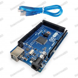
1 x Arduino Mega 2560 CH340
1 x Cable for Arduino Mega 2560.
RoboticsBD RoboticsBD RoboticsBD RoboticsBD RoboticsBD RoboticsBD RoboticsBD RoboticsBD RoboticsBD RoboticsBD
RoboticsBD RoboticsBD RoboticsBD RoboticsBD RoboticsBD RoboticsBD RoboticsBD RoboticsBD RoboticsBD RoboticsBD
The latest price of Arduino Mega 2560 CH340 in Bangladesh is BDT 1,498 You can buy the Arduino Mega 2560 CH340 at best price from our RoboticsBD or visit RoboticsBD Office.
|
Please note that the product information provided on our website may not be entirely accurate as it is collected from various sources on the web. While we strive to provide the most up-to-date information possible, we cannot guarantee its accuracy. We recommend that you always read the product labels, warnings, and directions before using any product. |
|
Product Images are shown for illustrative purposes only and may differ from the actual product. |

Reference: RBD-0009
54 Digital I/O terminals (14 of which have programmable PWM outputs). 16 Analog Inputs. 4 UARTs (hardware serial ports). 16 MHz crystal clock. RoboticsBD Operating voltage: 6 ~ 12v. Dimensions: 110 x 53 x 15 mm.
Reference: RBD-0094
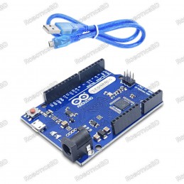
The Arduino Uno R3 High-Quality Edition Arduino UNO in Bangladesh Micro-controller : ATmega328. Operating Voltage : 5V. Input Voltage (recommended) : 7-12V. Digital I/O Pins : 14 (of which 6 provide PWM output). Analog Input Pins : 6. The Arduino Uno R3 High-Quality Edition embodies superior craftsmanship and meticulous attention to detail, resulting in...
Reference: RBD-0436
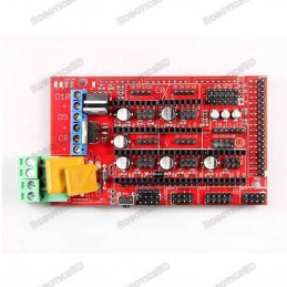
Supply Voltage: 12V Standard interfaces (as that of the extruder) Reserved GCI like I2C and RS232 3 MOSFET’s are applied to the heater/ fan and thermistor circuit. Another 5A added to protect the component parts. An 11A fuse is added to the hotbed. Support 5 stepper drive board
Reference: RBD-1214
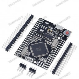
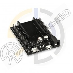
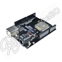
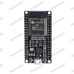
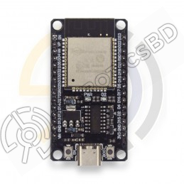
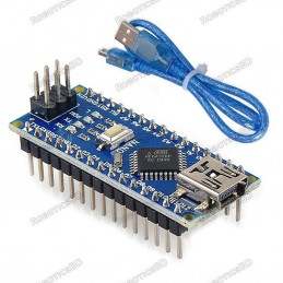
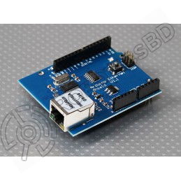
The board is compatible with Mega 2560. excellent solution for developing projects based on ATmega2560. The board can be powered directly through the Micro USB connector The maximum output current upon 5V is around 800mA, while on the 3.3V it is about 800mA.
Reference: RBD-2199
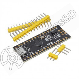
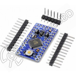
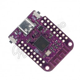
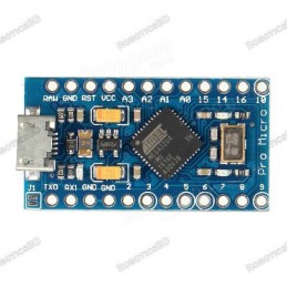
Compatible with the Arduino IDE, making it easy for beginners to start using Smaller and cheaper than traditional Arduino boards Powered by a 16.0 MHz microcontroller Fully assembled except for headers, allowing for easy soldering Great for projects where size and cost are a concern Perfect for beginners to jump into electronics Can be used for a variety...
Reference: RBD-1218
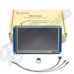
Model No.:NX8048T050 Display Type:011R(R:Resitive Touchscreen) Operating Voltage (VDC):4.75 ~ 7 Max. Operating Current (mA):410 Touch Type: Resistive Colors:65K (65536)
Reference: RBD-1812
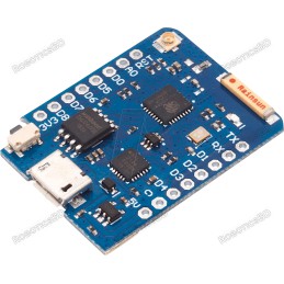
11 digital input/output pins Interrupt/PWM/I2C/one-wire 1 analog input(3.2V max input) 16M bytes(128M bit) Flash External antenna connector Built-in ceramic antenna New CP2104 USB-TO-UART IC
Reference: RBD-2271
Wide compatibility with ESP32-DevKitC(30P) series boards Safe and reliable with stable power and signal transmission Extended GVS interface for easy connection to various electronic modules and sensors JUMP interface for easy reuse of all pins, making it ideal for DIY projects Versatile and reliable option suitable for a wide range of projects
Reference: RBD-2126
Manufacturer: China Support TWI and SPI communication Input voltage (recommended) range from 7V to 12V Input Voltage (limit) range from 6V to 20V 20 digital input/output pins (of which 7 can be used as PWM outputs and 12 as analog inputs) Onboard ATmega32u4 microcontroller with 32KB flash memory, 2.5KB SRAM and 1KB EEPROM
Reference: RBD-1214
The board is compatible with Mega 2560. excellent solution for developing projects based on ATmega2560. The board can be powered directly through the Micro USB connector The maximum output current upon 5V is around 800mA, while on the 3.3V it is about 800mA.
Reference: RBD-0658
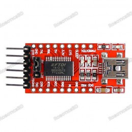
Standard interface layout, compatible with a variety of Arduinos such as the Pro Mini Original FTDI FT232 chip, stable performance USB power has current protection, using 500MA self-restore fuse RXD/TXD transceiver communication indicator With power, sending, receiving indicator, working status LED indicators Mini USB Port Connection Support 3.3V, 5V...
Reference: RBD-2164
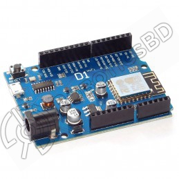
WeMos D1 R32 Mini ESP32 WIFI Bluetooth Development Board CH340 chip for compatibility with Arduino UNO R3 Supports WIFI and Bluetooth connectivity Comes with a Type-B/Micro USB adapter
Reference: RBD-0155
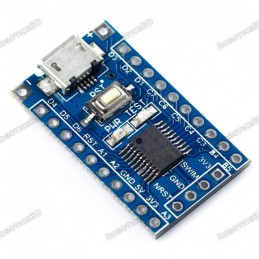
Microcontroller: ATmega328 Circuit Operating Voltage: 5V Clock frequency: 16MHz. Digital I/O Pins: 14 8 analog input port: A0 ~ A7. A pair of TTL level serial port transceiver : RX / TX. 6 PWM port: D3, D5, D6, D9, D10, D11. Support serial download.
Reference: RBD-1827
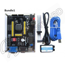
Altera Cyclone IV EP4CE6 FPGA Development Board NIOSII EP4CE PCB USB Blaster Jtag AS Programmer
Reference: RBD-2138
Arduino compatibility Full integration USB-TTL converter 32 Mb flash memory Dual microcontrollersA high-quality USB cable is essential for this board to ensure sufficient current supply; otherwise, your board may not be recognized by the Windows Device Manager. Please avoid using mobile phone cables and instead use the recommended cable available here:...
Reference: RBD-2243
Wearable e-textile technology. Designed with large sew tabs Button Board
Reference: RBD-1216
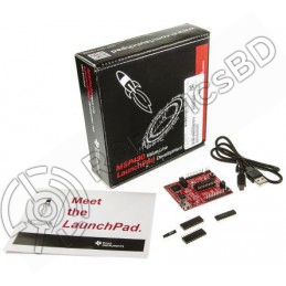
14-/20-pin DIP (N) Socket 20 pin LaunchPad standard leveraging the BoosterPack ecosystem On-Board EZ-FET emulator featuring EnergyTrace™ technology Supports MSP430G2xx2, MSP430G2xx3, and MSP430F20xx devices in PDIP14 or PDIP20 packages 1 user buttons and 3 LEDs for user interaction
Reference: RBD-1806
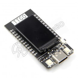
Based on ESP32 240MHz Xtensa dual-core 32-bit microprocessor Operating Voltage: 2.7V – 4.2V Working Current: 60mA Battery Charging Current: 500mA
Reference: RBD-2240
Wearable e-textile technology. Designed with large sew tabs LED Green Color
Reference: RBD-0948
Built-in Flash: 32Mbit Power supply: 5V WiFi protocol: IEEE 802.11 b/g/n Peripheral interface: UART/GPIO/ADC/DAC/SDIO/PWM/I2C/I2S Logic level: 3.3V A high-quality USB cable is essential for this board to ensure sufficient current supply; otherwise, your board may not be recognized by the Windows Device Manager. Please avoid using mobile phone cables and...
Reference: RBD-1820
38 Pin version 2.4GHz Dual-Mode WiFi + Bluetooth Development Board, 38PIN Ultra-Low power consumption works perfectly with the IDE A high-quality USB cable is essential for this board to ensure sufficient current supply; otherwise, your board may not be recognized by the Windows Device Manager. Please avoid using mobile phone cables and instead use the...
Reference: RBD-2266
Versatile and powerful development board for IoT and embedded systems projects. USB Type-C port for reversible plug orientation and easy connection to computer or other devices. Built-in Wi-Fi and Bluetooth module for wireless connectivity. Arduino IDE compatibility for easy code writing and uploading. Suitable for a wide range of applications, including...
Reference: RBD-1602
Microcontroller: ESP8266EX Operating Voltage: 3.3V Digital I/O Pins: 11 (all I/O pins have interrupt/PWM/I2C/one-wire capability, except for D0) Analog Input Pins: 1 Flash Memory: 4MB On-Board Switching Power Supply: Input Voltage Range: 9V to 12V Output: 5V at 1A Max
Reference: RBD-2131
ESP32-S2 based WIFI development board Features S2FN4R2 WIFI IC Equipped with 4MB FLASH and 2MB PSRAM Type-C USB connectivity 27 digital input/output pins with support for interrupt/pwm/I2C/single wire ADC, DAC, I2C, SPI, UART, USB OTG
Reference: RBD-2053
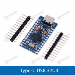
ATMEGA32U4 running in 5V / 16MHz Support Arduino IDE V1.0.1 Micro USB interface programming on the board Four 10-bit ADC pin 12 digital I / O (5 PWM capability) Rx and Tx hardware serial connection. RoboticsBD
Reference: RBD-0682
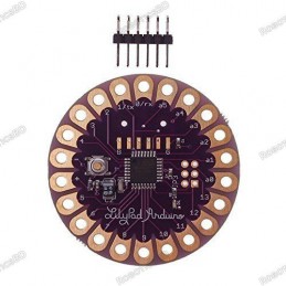
Microcontroller: ATmega168 or ATmega328V Operating Voltage: 2.7-5.5 V Digital I/O Pins: 14 PWM Channels: 6 Analog Input Channels: 6 DC Current per I/O Pin: 40 mA Board will run from 2V to 5V. The latest version of the LilyPad supports automatic reset for even easier programming. The back side of the LilyPad is now completely flat! RoboticsBD
Reference: RBD-2162
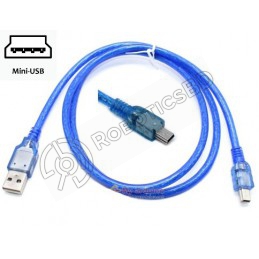
USB Type: Type-A to Mini-B Length: 1 meter/ 3.2 Feet Exclusively designed for Arduino boards. Compatible with Arduino Nano Larger Cable
Reference: RBD-1684
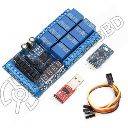
8 Channel DC 12V Pro mini Relay Shield Module PLC Timer Board for Arduino
Reference: RBD-0838
ATMEGA32U4 running in 5V / 16MHz Support Arduino IDE V1.0.1 Micro USB interface programming on the board Four 10-bit ADC pin 12 digital I / O (5 PWM capability) Rx and Tx hardware serial connection. RoboticsBD
Reference: RBD-0576
Chipboard STM32F103C8T6 On board, SWIM interface and reset button Micro USB line or the 2.54 pin to link to the power with the input voltage 4.5V-15V. Power light and the Demo indicator light Leads all the pins and has detailed label for the Pins. Support SWIM debug mode. RoboticsBD
Reference: RBD-0154
Microcontroller: ATmega32u4 Operating Voltage: 5V Input Voltage (Recommended): 7-12V Input Voltage (limits): 6-20V Digital I/O Pins: 20 PWM Channels: 7 Analog Input Channels: 12
Reference: RBD-2268
Features WiFi+Bluetooth connectivity with the ESP-WROOM-32 module Accessible I/O pins via extension headers for easy customization Onboard USB CH340 for convenient programming and debugging 2x keys for reset or user-defined functions ESP32S-DEV development board is a cost-effective solution for a wide range of applications.A high-quality USB cable is...
Reference: RBD-1821
Open-source, Interactive, Programmable, Low cost, Simple, Smart, WI-FI enabled Arduino-like hardware IO Integrated TR switch, balun, LNA, power amplifier and matching network Integrated PLL, regulators, DCXO and power management units Onboard USB to serial chip to easily program and upload codes from the Arduino IDE Easy to use breadboard friendly form...
Reference: RBD-2137
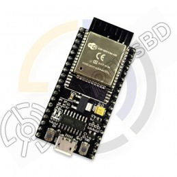
ESP32 Development Board Integrated antenna and RF balun Dual-mode Wi-Fi and Bluetooth chips Small size and high performance-price ratio Compatible with Arduino
Reference: RBD-1202
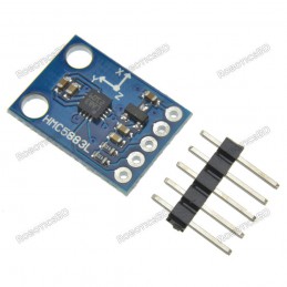
3-axis magnetic electronic compass. Precise heading information. Operating Voltage: 3 -5 V DC. Driver Chip: HMC5883L / QMC5883L Communication: I2C protocol. Measuring range: ± 1.3-8 Gauss.Library: https://github.com/keepworking/Mecha_QMC5883Lhttps://www.arduino.cc/reference/en/libraries/qmc5883lcompass/
Reference: RBD-0770
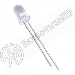
Size: 5mm Color: Yellow Head Shape: Round Lens Appearance: Transparent
Reference: RBD-1061
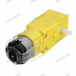
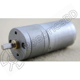
BO Series motor with 100-150 RPM options Operates at 6V, ideal for small to medium robots Lightweight, easy to install with mounting holes Suitable for DIY projects and mobile robot cars Cost-effective with plastic gear construction
Reference: RBD-0654
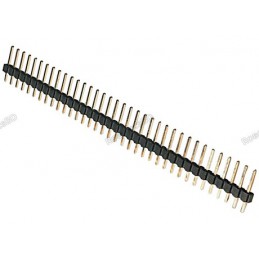
Single row. 2.54mm pitch. 1 x 40 pins. Through-hole mount. RoboticsBD
Reference: RBD-1299
Size: 5mm Color: White Head Shape: Round Lens Appearance: Transparent
Reference: RBD-2094
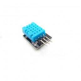
The module can detect the surrounding environment of the humidity and temperature High reliability and excellent long-term stability The output from the digital output Humidity measuring range: 20%~90%RH(0~50 degree (temperature compensation). Temperature measuring range: 0~+50degree. Humidity measurement accuracy: ±5.0%RH. Temperature measurement...
Reference: RBD-0948
Built-in Flash: 32Mbit Power supply: 5V WiFi protocol: IEEE 802.11 b/g/n Peripheral interface: UART/GPIO/ADC/DAC/SDIO/PWM/I2C/I2S Logic level: 3.3V A high-quality USB cable is essential for this board to ensure sufficient current supply; otherwise, your board may not be recognized by the Windows Device Manager. Please avoid using mobile phone cables and...
Reference: RBD-0523
Module Power: 5.00V Module Size : 43 x 32mm(1.69×1.26″) Measuring Range :0 – 14PH Measuring Temperature: 0 – 60 ℃ Accuracy : ± 0.1pH (25 ℃)
Reference: 0031
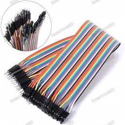
3 Types Available (Please select from option) 1. Male to Male 2. Male to Female 3. Female-Female
Reference: RBD-0022
This is the HC-SR04 ultrasonic distance sensor. This economical sensor provides 2cm to 400cm of non-contact measurement functionality with a ranging accuracy that can reach up to 3mm. Each HC-SR04 module includes an ultrasonic transmitter, a receiver and a control circuit. There are only four pins that you need to worry about on the HC-SR04: VCC (Power),...
Reference: RBD-0020
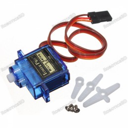
Model: SG90 Weight: 9 gm Operating voltage: 3.0V~ 7.2V Servo Plug: JR Stall torque @4.8V : 1.2kg-cm Stall torque @6.6V : 1.6kg-cm Note: Product images/ Components brand may vary from actual product as our stock rotates.
Reference: RBD-0133
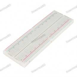
830 Solder-less Points Ideal for Experimenting With Circuit Design In Labs Compatible with resistance, diodes, transistors, LED’s, Capacitors and other types of electronic components Colored coordinates for easy components placement. Accept a variety of wire sizes 20-29 AWG
Reference: RBD-0376
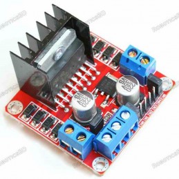
Current Sense for each motor. RoboticsBD Heatsink for better performance. Power-On LED indicator. Double H bridge Drive Chip: L298N. Operating Voltage(VDC): 5~35 Peak Current (A): 2 Continuous Current (A): 0-36mA No. of Channels: 2 Over-Current Protection (A): Yes Thermal Protection: Yes
Reference: RBD-0685
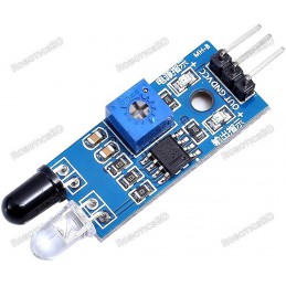
Detection distance: 2 ~ 30cm Detection angle: 35 ° Comparator chip: LM393 3mm screw holes for easy mounting
Reference: 0245
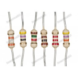
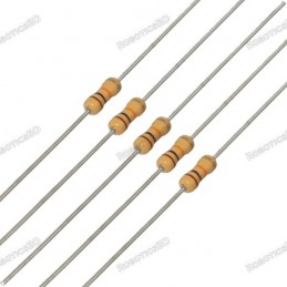
Choose your desire Resistor value from below:
Reference: RBD-0094
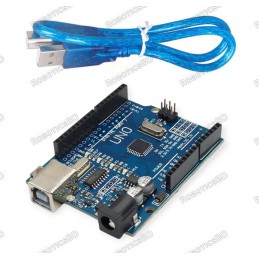
The Arduino Uno R3 High-Quality Edition Arduino UNO in Bangladesh Micro-controller : ATmega328. Operating Voltage : 5V. Input Voltage (recommended) : 7-12V. Digital I/O Pins : 14 (of which 6 provide PWM output). Analog Input Pins : 6. The Arduino Uno R3 High-Quality Edition embodies superior craftsmanship and meticulous attention to detail, resulting in...
Reference: RBD-0323
Microcontroller ATmega328 (SMD) – Interface CH340G Operating Voltage: 5V Input Voltage (recommended): 7-12V Digital I / O Pins 14 (of which 6 provide PWM output) RoboticsBD Analog Input Pins: 6 A programming cable is included.
Reference: RBD-0350
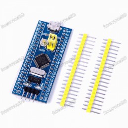
100% Brand new and high quality STM32 Board Model: STM32F103C8T6. Core: ARM 32 Cortex-M3 CPU. Debug mode: SWD. 72MHz work frequency. 64K flash memory, 20K SRAM. RoboticsBD 2.0-3.6V power, I/O.
Reference: RBD-2138
Arduino compatibility Full integration USB-TTL converter 32 Mb flash memory Dual microcontrollersA high-quality USB cable is essential for this board to ensure sufficient current supply; otherwise, your board may not be recognized by the Windows Device Manager. Please avoid using mobile phone cables and instead use the recommended cable available here:...
Reference: RBD-2268
Features WiFi+Bluetooth connectivity with the ESP-WROOM-32 module Accessible I/O pins via extension headers for easy customization Onboard USB CH340 for convenient programming and debugging 2x keys for reset or user-defined functions ESP32S-DEV development board is a cost-effective solution for a wide range of applications.A high-quality USB cable is...
Reference: RBD-0009
54 Digital I/O terminals (14 of which have programmable PWM outputs). 16 Analog Inputs. 4 UARTs (hardware serial ports). 16 MHz crystal clock. RoboticsBD Operating voltage: 6 ~ 12v. Dimensions: 110 x 53 x 15 mm.
Reference: RBD-1214
The board is compatible with Mega 2560. excellent solution for developing projects based on ATmega2560. The board can be powered directly through the Micro USB connector The maximum output current upon 5V is around 800mA, while on the 3.3V it is about 800mA.
Reference: RBD-0032
USB Driver: CH340 Operating Voltage (logic level): 5V With Mini USB 8 analog inputs ports: A0 ~ A7 14 Digital input / output ports: TX, RX, D2 ~ D13 1 pair of TTL level serial transceiver ports RX / TX Using Atmel Atmega328P-AU MCU There is a bootloader installed in it Standard 0.1” spacing DIP (breadboard friendly). Manual reset switch. Please select...