
Product Images are shown for illustrative purposes only and may differ from the actual product.


 Store Pickup Available!
 Free Ship Over 5000 BDT
 Quality Product
 No Warranty
 No Replacement
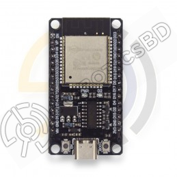
ESP32-S2-DevKitM-1 is entry-level development board. Most of the I/O pins on the module are broken out to the pin headers on both sides for easy interfacing. Developers can either connect peripherals with jumper wires or mount ESP32-S2-DevKitM-1 on a breadboard.. Featured By RoboticsBD.
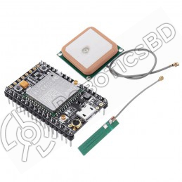
ESP32-S2-MINI-1 and ESP32-S2-MINI-1U are two powerful, generic Wi-Fi MCU modules that have a rich set of peripherals. They are an ideal choice for a wide variety of application scenarios related to Internet of Things (IoT), such as wearable electronics and smart home Featured By RoboticsBD.
Product Images are shown for illustrative purposes only and may differ from the actual product.
Note: Product images/ Components brand may vary from actual product as our stock rotates.
Featured By RoboticsBD.
| Key Component | Description |
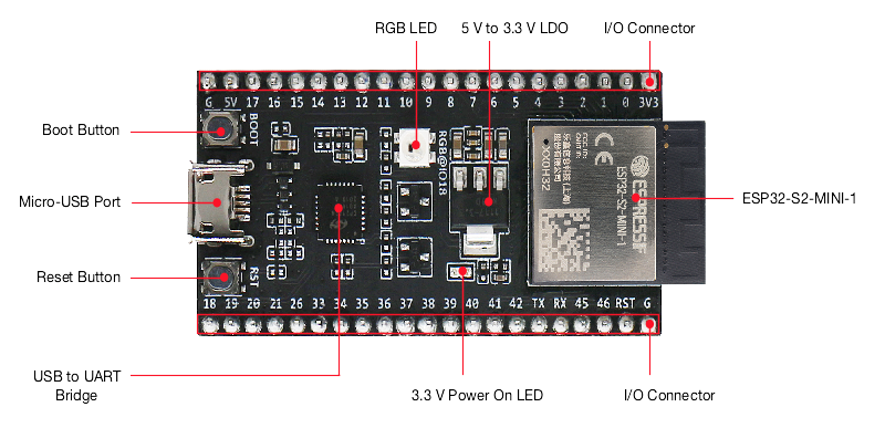
| On-board module (ESP32-S2-MINI-1 or ESP32-S2-MINI-1U in figures above) | ESP32-S2-MINI series modules with an on-board PCB antenna or a connector for an external antenna. This series of modules, known for its small size, have a flash and/or a PSRAM integrated in the chip package. For more information, please refer to Ordering Information. |
| Pin Headers | All available GPIO pins (except for the SPI bus for flash) are broken out to the pin headers on the board. Users can program ESP32-S2FH4 chip to enable multiple functions such as SPI, I2S, UART, I2C, touch sensors, PWM etc. For details, please see Header Block. |
| 3.3 V Power On LED | Turns on when the USB power is connected to the board. |
| USB to UART Bridge | Single USB-UART bridge chip provides transfer rates up to 3 Mbps. |
| Reset Button | Reset button. |
| Micro-USB Port | USB interface. Power supply for the board as well as the communication interface between a computer and the ESP32-S2FH4 chip. |
| Boot Button | Download button. Holding down Boot and then pressing Reset initiates Firmware Download mode for downloading firmware through the serial port. |
| RGB LED | Addressable RGB LED, driven by GPIO18. |
| 5 V to 3.3 V LDO | Power regulator that converts a 5 V supply into a 3.3 V output. |
| External Antenna Connector | On ESP32-S2-MINI-2U and ESP32-S2-MINI-1U module only. For connector dimensions, please refer to Section External Antenna Connector Dimensions in module datasheet. |
Featured By RoboticsBD.
| General Specification | |
| Microprocessor | ESP32-S2FH4 chip, Xtensa single-core 32-bit LX7 |
| ROM | 128 KB |
| SRAM | 320 KB |
| SRAM | 16 KB RTC |
| crystal oscillator | 40 MHz |
| SPI flash | 4 MB |
| Operating Voltage/Power supply | 3.0~3.6 V |
| Operating Temperature Range | –40~85°C |
| Shipment Weight | 0.011 kg |
| Shipment Dimensions | 8 × 7 × 2 cm |
Please allow 5% measuring deviation due to manual measurement.
1 x ESP32-S2-DevKitM-1 Development Board
The latest price of ESP32-S2-DevKitM-1 Development Board in Bangladesh is BDT 2,190 You can buy the ESP32-S2-DevKitM-1 Development Board at best price from our RoboticsBD or visit RoboticsBD Office.
|
Please note that the product information provided on our website may not be entirely accurate as it is collected from various sources on the web. While we strive to provide the most up-to-date information possible, we cannot guarantee its accuracy. We recommend that you always read the product labels, warnings, and directions before using any product. |
|
Product Images are shown for illustrative purposes only and may differ from the actual product. |

Reference: RBD-1407
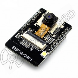
Flash LED off: 180mA @ 5V. Flash LED on to maximum brightness: 310mA @ 5V. Deep-sleep: 6mA @ 5V min. Modem-sleep: 20mA @ 5V min. Light-sleep: 6.7mA @ 5V min. Programmer: ESP32-CAM-MB MICRO USB Download Module The ESP32 CAM does not come pre-assembled with the camera. You'll need to connect the camera ribbon cable to the board, a task which can be...
Reference: RBD-1412
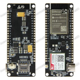
Chipset :ESPRESSIF-ESP32 240MHz Xtensa® single-/dual-core 32-bit LX6 microprocessor FLASH: QSPI flash 4MB / PSRAM 8MB SRAM:520 kB SRAM Button: Reset USB to TTL: CP2104 Modular interface: UART,SPI,SDIO,I2C,PWM,TV PWM,I2S,IRGPIO On-board clock:40MHz crystal oscillator Working voltage:2.7V-3.6V Working current: About 70mA
Reference: RBD-1558
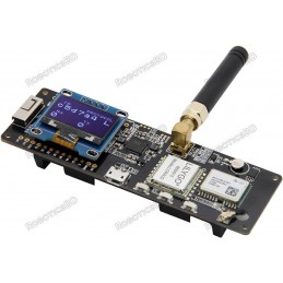
TTGO Meshtastic T-Beam V1.1 ESP32 915Mhz or 433Mhz (Ships Random) WiFi Bluetooth ESP32 GPS NEO-6M SMA 18650 Battery Holder OLED (915Mhz OLED)
Reference: RBD-1671
ESP32 Bluetooth Wi-Fi development board, support NodeMCU / Arduino DHT11 temperature and humidity sensor CP2104 communication chip USB TO TTL Micro USB port Soil probe (long) soil temperature and humidity detection module 18650 Lithium Battery Holder Powered (Battery is not included)
Reference: RBD-1765
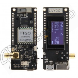
LILYGO TTGO Model: 915MHZ CH9102F T3_V1.6.1 LoRa32 V2.1_1.6 Version 915Mhz ESP32 LoRa OLED 0.96 Inch SD Card Bluetooth WIFI Wireless Module ESP-32 SMA
Reference: RBD-1806
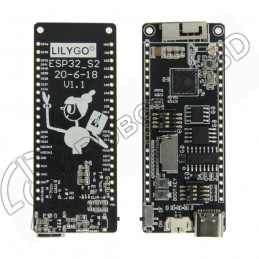
Based on ESP32 240MHz Xtensa dual-core 32-bit microprocessor Operating Voltage: 2.7V – 4.2V Working Current: 60mA Battery Charging Current: 500mA
Reference: RBD-1852
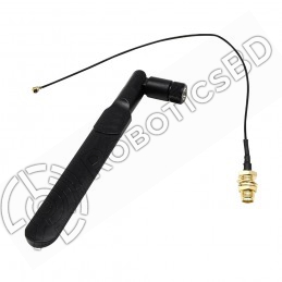
IPEX To SMA Female External Antenna Adapter SMA Male Antenna for 2.4G WIFI Module Only Antenna and Adapter RF Cable ESP32 Cam is not included
Reference: RBD-1945
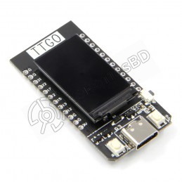
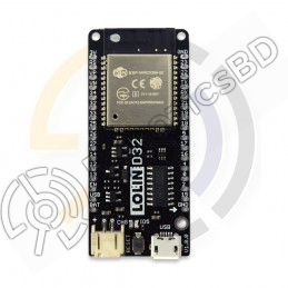
TTGO module from LilyGO Microcontroller based on an ESP32-S2 chip. USB-C connection MicroSD card adapter.
Reference: RBD-2044
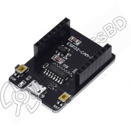
Model: ESP32-CAM-MB Color: Black Chipset: CH340G Connectivity Technology: USB Note: The camera module is not included with the board.
Reference: RBD-2176
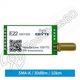
LoRa module based on Semtech SX1262 RF chip Supports automatic relay networking Long transmission distance up to 10 km Low power consumption Small size
Reference: RBD-0960
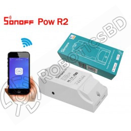
Voltage range: 100-240V AC Color: White Remote Control Monitor Energy Usage Historical Energy Consumption Overload Protection Measure Power Usage for a Period Sync Status Timing Function Share Control Smart Scene APP Supported Check out New Product Sonoff POWR320D Elite Smart Power Meter Switch
Reference: RBD-1670
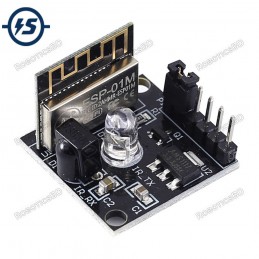
The smallest 802.11b/g/n Wi-Fi SoC module Uses low power 32bit CPU and compatible with the application processor Main frequency up to 160MHz Built-in 10Bit high precision ADC Support UART/GPIO/PWM/ADC interface Integrate Wi-Fi MAC/BB/RF/PA/LNA
Reference: RBD-1603
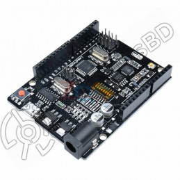
USB-TTL converter. Logic Level: 5V. Operating Supply Voltage: 5V. Digital I/O Pins: 14. Analog I/O Pins: 6.
Reference: RBD-1661
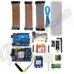
All in one kit for Arduino Based Wireless and IoT NRF wireless Transceiver Module Sim900 Shield Sim800L RF Transmitter and Receiver
Reference: RBD-1671
ESP32 Bluetooth Wi-Fi development board, support NodeMCU / Arduino DHT11 temperature and humidity sensor CP2104 communication chip USB TO TTL Micro USB port Soil probe (long) soil temperature and humidity detection module 18650 Lithium Battery Holder Powered (Battery is not included)
Reference: RBD-2044
Model: ESP32-CAM-MB Color: Black Chipset: CH340G Connectivity Technology: USB Note: The camera module is not included with the board.
Reference: RBD-1729
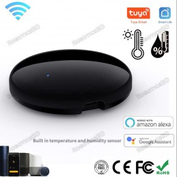
Tuya Smart Universal IR Remote Control your Air Conditioner TV AC Works with Alexa, Google Home
Reference: RBD-1255
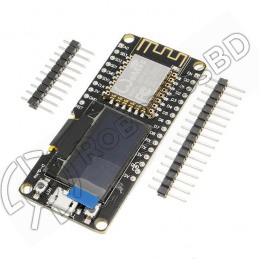
Integrated 0.96″ OLED Micro USB connection Compatible with Arduino Compatible with NodeMCU(Lua for ESP8266) Input Power 5V Compatible for Arduino Compatible with NodeMCU(Lua for ESP8266)A high-quality USB cable is essential for this board to ensure sufficient current supply; otherwise, your board may not be recognized by the Windows Device Manager. Please...
Reference: RBD-1407
Flash LED off: 180mA @ 5V. Flash LED on to maximum brightness: 310mA @ 5V. Deep-sleep: 6mA @ 5V min. Modem-sleep: 20mA @ 5V min. Light-sleep: 6.7mA @ 5V min. Programmer: ESP32-CAM-MB MICRO USB Download Module The ESP32 CAM does not come pre-assembled with the camera. You'll need to connect the camera ribbon cable to the board, a task which can be...
Reference: RBD-1945
TTGO module from LilyGO Microcontroller based on an ESP32-S2 chip. USB-C connection MicroSD card adapter.
Reference: RBD-2108
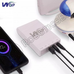
Multiple Outputs: 5V+9V+12V Constant DC output, long backup time up to 6 hours Intelligent circuit design with over-charging, over-discharging and short circuit protections Suitable for 95% DC/USB digital products, such as: modem, router, CCTV camera, mobile phone etc.
Reference: RBD-2164
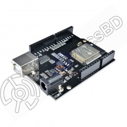
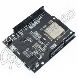
WeMos D1 R32 Mini ESP32 WIFI Bluetooth Development Board CH340 chip for compatibility with Arduino UNO R3 Supports WIFI and Bluetooth connectivity Comes with a Type-B/Micro USB adapter
Reference: RBD-2270
Powerful and versatile ESP32 SoC with WiFi and Bluetooth connectivity 4MB of flash memory and 520KB of SRAM for storing firmware and data Compatible with the Arduino development environment for easy programming Input/output pins for connecting to sensors, actuators, and other peripherals Can be programmed using MicroPython, a high-level programming...
Reference: RBD-0698
On-board level shift circuit Arduino UNO R3 and the compatible board can directly connect to this module; Interface logic voltage: 3.3V / 5V compatible(On-board level shift circuit); Working voltage: 4.5~5.5V (Onboard 3.3V LDO Regulator); Working current: 240mA(MAX).RoboticsBD
Reference: RBD-0697
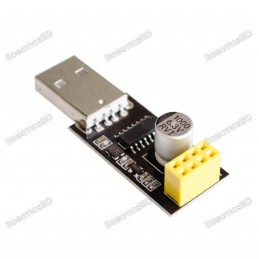
Driver Chip: CH340G Supports all basic windows versions. The adapter plate integrated 1000μF solid capacitors to ensure the current supply The power supply will not be a problem to make WIFI module crashes unresponsive. Using 3225 SMD crystal oscillator, improve the stability of serial work, on a beautiful and tall. Working voltage: 4.5V – 5.5V (Onboard...
Reference: RBD-1531
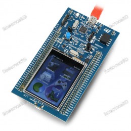
The commissioning kit is based on the board STM32f429zit6 (180 MHz, 2 MB of Flash memory, 256 KB RAM, Cortex-M4F ARM). On-Board is also 3-axis gyroscope, touchscreen LCD 2.4" QVGA TFT and programmer / debugger ST-LINK/V2-B.
Reference: RBD-1641
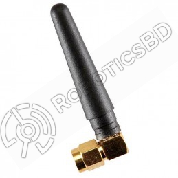
Product: GSM Antenna Color: Black SMA male straight 5cm 900-1800MHz radio antenna. Frequency: 900MHz – 1800MHz Maximum Power: 50W Length: 5cm/1.97 inch
Reference: RBD-1337
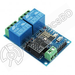
Transmission Distance(m) :400 Relay Channel:2 Trigger Voltage (VDC): 5 Switching Voltage (VAC):250@10A Switching Voltage (VDC):30@10A Baud Rate:9600 Note: Relay might be different from the picture as per stock
Reference: RBD-1176
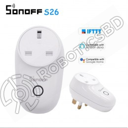
Power supply: 90V~250V AC(50/60Hz) Max. Current: 10A Remote turn on/off connected device. Support checking real-time device status on APP. Support scheduled/countdown/loop timing tasks. Setting scene to turn on/off a group of devices in the same account. Setting scene to trigger on/off the other device by status changes
Reference: RBD-1558
TTGO Meshtastic T-Beam V1.1 ESP32 915Mhz or 433Mhz (Ships Random) WiFi Bluetooth ESP32 GPS NEO-6M SMA 18650 Battery Holder OLED (915Mhz OLED)
Reference: RBD-1672
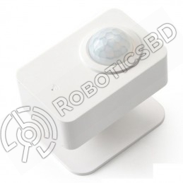
Model Number: P06 Product Name: PIR Sensor Indoor Communication: greater than 20 Meters Detect Angle Side View: 128 degrees Detect Angle Down View: 128 degrees Detect distance: 10 Meters<
Reference: RBD-2142
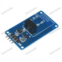
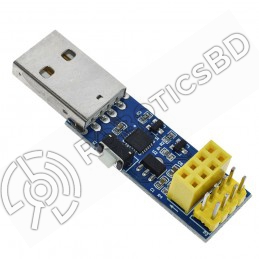
Operating Voltage: 5VDC USB to Serial Converter: CH340C Compatible With:ESP8266 ESP-01/01S Comes With Onboard Reset Switch Has Female Headers for Connecting the Wifi Module.
Reference: RBD-2137
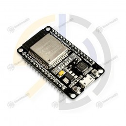
ESP32 Development Board Integrated antenna and RF balun Dual-mode Wi-Fi and Bluetooth chips Small size and high performance-price ratio Compatible with Arduino
Reference: RBD-2267
Integrated Wi-Fi and Bluetooth connectivity make this board a great choice for IoT projects and robotics. The ESP32 chip on the board is a dual-core microcontroller that operates at up to 240 MHz, providing ample processing power for complex projects. With 520 KB of SRAM and 4 MB of flash memory, the board has plenty of memory for storing and running...
Reference: RBD-1557
USB communication, no need write code Support PC software automation Double antenna Support quad-band, universal worldwide Support 2G/3G/4G Automatically connect to the network Adaptive frequency
Reference: RBD-2266
Versatile and powerful development board for IoT and embedded systems projects. USB Type-C port for reversible plug orientation and easy connection to computer or other devices. Built-in Wi-Fi and Bluetooth module for wireless connectivity. Arduino IDE compatibility for easy code writing and uploading. Suitable for a wide range of applications, including...
Reference: RBD-1566
Long distance APP remote control via WIFI; Support routing mode (AP) and LAN connection mode (STA); Support almost every kind of one-wire or two-wire LED driver IC; Brightness adjustable, with 180 kinds of patterns and 8 kind of color adjustable patterns;
Reference: RBD-2131
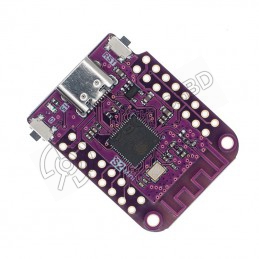
ESP32-S2 based WIFI development board Features S2FN4R2 WIFI IC Equipped with 4MB FLASH and 2MB PSRAM Type-C USB connectivity 27 digital input/output pins with support for interrupt/pwm/I2C/single wire ADC, DAC, I2C, SPI, UART, USB OTG
Reference: RBD-1402
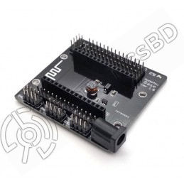
The perfect solution for breaking out the pins from Lua V3 Nodemcu. Lead-out all the IO ports of the ESP-12E development board Lead out the pins of 5V and 3.3V power supply Convenient to connect with peripheral modules Onboard 5V / 1A DC-DC step-down converter circuit Onboard power indicator With DC power jack 6-24V.
Reference: RBD-0664
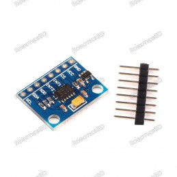
Supply Voltage: 3.3 V/ 5V. Interface Type: I²C, SPI. Sensing Range: ±2g, ±4g, ±8g, ±16g. Sensitivity X: 28.6 LSB/g. Sensitivity Y: 31.2 LSB/g. Sensitivity Z: 34.5 LSB/g. Ultra Low Power: 40µA in measurement mode, 0.1µA in standby@ 2.5V. Free-Fall Detection. Tap/Double Tap Detection. RoboticsBD
Reference: RBD-0120
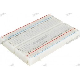
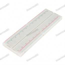
400 tie points 2 Power lanes, Total 100 tie points in power lanes 1 Double strip, Total 300 tie points Perfect for Arduino shield prototyping and testing Plastic housing, metal contact clips
Reference: RBD-0840
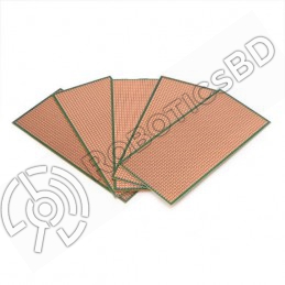
Dimension: 14.5×6 cm Copper Thickness 1-4 OZ Board Thickness 1.1 mm Board color: Brown
Reference: RBD-1832
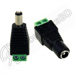
Simple & professional appearance for power cabling. Easy camera installation, saves time and provides more secure cable connection. No electrical tape, no splicing, no crimping - only a small screw driver needed.
Reference: RBD-1646
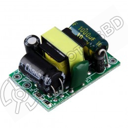
Input Voltage: 220VAC Output Voltage: 5 VDC. Output Power: 3.5W. Output overload and short circuit protection.
Reference: RBD-0094
The Arduino Uno R3 High-Quality Edition Arduino UNO in Bangladesh Micro-controller : ATmega328. Operating Voltage : 5V. Input Voltage (recommended) : 7-12V. Digital I/O Pins : 14 (of which 6 provide PWM output). Analog Input Pins : 6. The Arduino Uno R3 High-Quality Edition embodies superior craftsmanship and meticulous attention to detail, resulting in...
Reference: RBD-0994
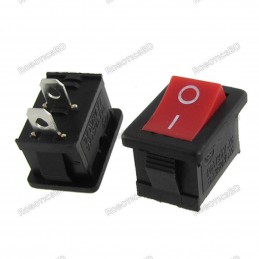
KCD1-101 10 Amp Rocker Switch 2 pin, ON-OFF, black and red color of button for your choice
Reference: RBD-1407
Flash LED off: 180mA @ 5V. Flash LED on to maximum brightness: 310mA @ 5V. Deep-sleep: 6mA @ 5V min. Modem-sleep: 20mA @ 5V min. Light-sleep: 6.7mA @ 5V min. Programmer: ESP32-CAM-MB MICRO USB Download Module The ESP32 CAM does not come pre-assembled with the camera. You'll need to connect the camera ribbon cable to the board, a task which can be...
Reference: RBD-0022
This is the HC-SR04 ultrasonic distance sensor. This economical sensor provides 2cm to 400cm of non-contact measurement functionality with a ranging accuracy that can reach up to 3mm. Each HC-SR04 module includes an ultrasonic transmitter, a receiver and a control circuit. There are only four pins that you need to worry about on the HC-SR04: VCC (Power),...
Reference: RBD-1349
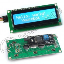
For Standard LCD 16x2. Press here.For Standard LCD 16x2 with Male Header. Press hereFor Standard LCD 16x2 with Female Header. Press hereFor Standard LCD 16x2 with I2C adapter board soldered. Press here.For Standard LCD 16x2 with White Background. Press here.For Standard LCD 16x2 with Blue Background. Press here. Model: LCD1602 Interface: I2C Interface...
Reference: 0031
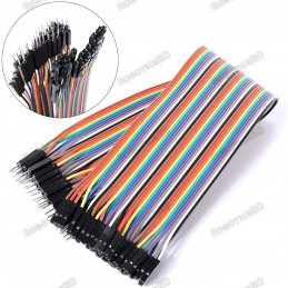
3 Types Available (Please select from option) 1. Male to Male 2. Male to Female 3. Female-Female
Reference: RBD-0094
The Arduino Uno R3 High-Quality Edition Arduino UNO in Bangladesh Micro-controller : ATmega328. Operating Voltage : 5V. Input Voltage (recommended) : 7-12V. Digital I/O Pins : 14 (of which 6 provide PWM output). Analog Input Pins : 6. The Arduino Uno R3 High-Quality Edition embodies superior craftsmanship and meticulous attention to detail, resulting in...
Reference: RBD-0133
830 Solder-less Points Ideal for Experimenting With Circuit Design In Labs Compatible with resistance, diodes, transistors, LED’s, Capacitors and other types of electronic components Colored coordinates for easy components placement. Accept a variety of wire sizes 20-29 AWG
Reference: RBD-0905
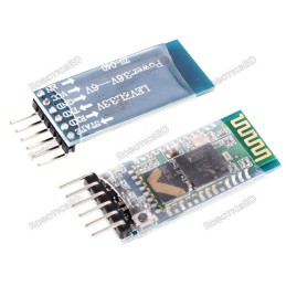
Bluetooth protocol: Bluetooth Specification v2.0+EDR. Frequency: 2.4GHz ISM band. Modulation: GFSK(Gaussian Frequency Shift Keying). Emission power: =4dBm, Class 2. Sensitivity: =-84dBm at 0.1% BER. RoboticsBD
Reference: RBD-0654
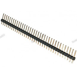
Single row. 2.54mm pitch. 1 x 40 pins. Through-hole mount. RoboticsBD
Reference: RBD-0318
This module is intended for advanced users who require moderate knowledge of GSM systems and microcontrollers. It needs wiring and firmware updates to unlock the country lock. Dual-Band 900/ 1800 MHz GPRS multi-slot class 10/8GPRS mobile station class B Compliant to GSM phase 2/2+ Dimensions: 24*24*3 mm Weight: 3.4g Control via AT commands (GSM 07.07...
Reference: RBD-0694
Power input: 4.5V ~ 9V (10VMAX), USB-powered Transfer rate: 110-460800bps Support UART / GPIO data communication interface Support Smart Link Smart Networking Working temperature: -40°C ~ + 125°C Drive Type: Dual high-power H-bridge Don’t need to download resetting A great set of tools to develop ESP8266 Flash size: 4MByte Lowest cost WI-FI Note: The...
Reference: RBD-2138
Arduino compatibility Full integration USB-TTL converter 32 Mb flash memory Dual microcontrollersA high-quality USB cable is essential for this board to ensure sufficient current supply; otherwise, your board may not be recognized by the Windows Device Manager. Please avoid using mobile phone cables and instead use the recommended cable available here:...
Reference: RBD-2176
LoRa module based on Semtech SX1262 RF chip Supports automatic relay networking Long transmission distance up to 10 km Low power consumption Small size
Reference: RBD-2268
Features WiFi+Bluetooth connectivity with the ESP-WROOM-32 module Accessible I/O pins via extension headers for easy customization Onboard USB CH340 for convenient programming and debugging 2x keys for reset or user-defined functions ESP32S-DEV development board is a cost-effective solution for a wide range of applications.A high-quality USB cable is...
Reference: RBD-1407
Flash LED off: 180mA @ 5V. Flash LED on to maximum brightness: 310mA @ 5V. Deep-sleep: 6mA @ 5V min. Modem-sleep: 20mA @ 5V min. Light-sleep: 6.7mA @ 5V min. Programmer: ESP32-CAM-MB MICRO USB Download Module The ESP32 CAM does not come pre-assembled with the camera. You'll need to connect the camera ribbon cable to the board, a task which can be...
Reference: RBD-0948
Built-in Flash: 32Mbit Power supply: 5V WiFi protocol: IEEE 802.11 b/g/n Peripheral interface: UART/GPIO/ADC/DAC/SDIO/PWM/I2C/I2S Logic level: 3.3V A high-quality USB cable is essential for this board to ensure sufficient current supply; otherwise, your board may not be recognized by the Windows Device Manager. Please avoid using mobile phone cables and...
Reference: RBD-1138
Board Based On AI-Thinker A9 GPRS Module Supports Firmware Upgrade Via Serial Port Operating Voltage: 5v