
Product Images are shown for illustrative purposes only and may differ from the actual product.


Note: Relay might be different from the picture as per stock
 Store Pickup Available!
 Free Ship Over 5000 BDT
 Quality Product
 No Warranty
 No Replacement
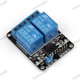
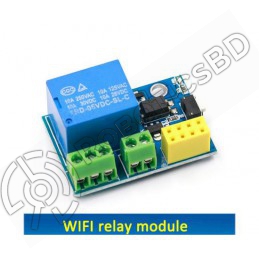
This Wi-Fi relay module carries an ESP8266 Wi-Fi module and microcontroller. It will send the serial port instructions to the cell phone APP and Implementation within the local area network (LAN) for wireless control relay. RoboticsBD
This module is ideally suited to controlling larger voltages in your project through WIFI. This is a 1 channel relay module that can be used to activate up to 250V AC and 30V DC. This allows you to build in device control, operating remote lights, or triggering systems when the module is supplied with a signal from an ESP8266 module. RoboticsBD
The module has an LED that lights relative to the state of the module. A red power activation LED that lights when a signal is received on the IN pin. When a signal is received an audible click can be heard as the relay triggers, connecting the output pins. The relay is controlled via the included ESP8266. This will require configuration via UART prior to full operation. Once it is programmed and powered it will look after itself, making it ideal for use in internet of things “IOT” based projects. Featured By RoboticsBD.
Product Images are shown for illustrative purposes only and may differ from the actual product.
RoboticsBD RoboticsBD RoboticsBD RoboticsBD RoboticsBD RoboticsBD RoboticsBD RoboticsBD RoboticsBD RoboticsBD
How to Use:
RoboticsBD RoboticsBD RoboticsBD RoboticsBD RoboticsBD RoboticsBD RoboticsBD RoboticsBD RoboticsBD RoboticsBD
| General Specification | |
| Transmission Distance(m) : | 400 |
| Relay Channel: | 2 |
| Trigger Voltage (VDC): | 5 |
| Switching Voltage (VAC): | 250@10A |
| Switching Voltage (VDC): | 30@10A |
| Baud Rate: | 9600 |
| Shipment Weight | 0.035 kg |
| Shipment Dimensions | 10 × 8 × 2 cm |
Please allow 5% measuring deviation due to manual measurement.
RoboticsBD RoboticsBD RoboticsBD RoboticsBD RoboticsBD RoboticsBD RoboticsBD RoboticsBD RoboticsBD RoboticsBD
1 x ESP8266 Dual WiFi Relay Module Internet Of Things Smart Home Mobile APP Remote Switch.
RoboticsBD RoboticsBD RoboticsBD RoboticsBD RoboticsBD RoboticsBD RoboticsBD RoboticsBD RoboticsBD RoboticsBD
RoboticsBD RoboticsBD RoboticsBD RoboticsBD RoboticsBD RoboticsBD RoboticsBD RoboticsBD RoboticsBD RoboticsBD
The latest price of ESP8266 Dual WiFi Relay Module Internet Of Things Smart Home Mobile APP Remote Switch in Bangladesh is BDT 835 You can buy the ESP8266 Dual WiFi Relay Module Internet Of Things Smart Home Mobile APP Remote Switch at best price from our RoboticsBD or visit RoboticsBD Office.
|
Please note that the product information provided on our website may not be entirely accurate as it is collected from various sources on the web. While we strive to provide the most up-to-date information possible, we cannot guarantee its accuracy. We recommend that you always read the product labels, warnings, and directions before using any product. |
|
Product Images are shown for illustrative purposes only and may differ from the actual product. |

Reference: RBD-0345
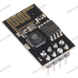
802.11 b/g/n Standards Wi-Fi Direct (P2P), soft-AP 1MB Flash Memory Integrated low power 32-bit CPU could be used as an application processor A-MPDU & A-MSDU aggregation & 0.4ms guard interval Wake up and transmit packets in < 2ms Standby power consumption of < 1.0mW (DTIM3) RoboticsBD
Reference: RBD-0408
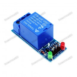
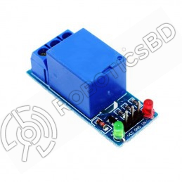
Low Level Trigger Relay Module. RoboticsBD Two separate LEDs for On/Off indication of the Relay. Triggering input voltage 3.3V – 5V Two separate LEDs for On/Off indication of the Relay Triggering input voltage 3.3V – 5V 4) Back EMF protection Back EMF protection 2 LEDs to indicate when relays are ON. Works with logic level signals from 3.3V or 5V devices...
Reference: RBD-0409
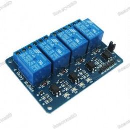
No. of Channel: 4 Trigger Voltage: 5VDC Triode drive, increasing relay coil High impedance controller pin Pull-down circuit for the avoidance of malfunction Power supply indicator and Control indicator lamp Power supply and relay instructions, lit, the disconnect is off; The input signal, signal, common Terminal and start conducting; RoboticsBD Note:...
Reference: RBD-0694
Power input: 4.5V ~ 9V (10VMAX), USB-powered Transfer rate: 110-460800bps Support UART / GPIO data communication interface Support Smart Link Smart Networking Working temperature: -40°C ~ + 125°C Drive Type: Dual high-power H-bridge Don’t need to download resetting A great set of tools to develop ESP8266 Flash size: 4MByte Lowest cost WI-FI Note: The...
Reference: RBD-0697
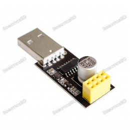
Driver Chip: CH340G Supports all basic windows versions. The adapter plate integrated 1000μF solid capacitors to ensure the current supply The power supply will not be a problem to make WIFI module crashes unresponsive. Using 3225 SMD crystal oscillator, improve the stability of serial work, on a beautiful and tall. Working voltage: 4.5V – 5.5V (Onboard...
Reference: RBD-0702
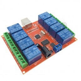
It has a relay status indicator led Power LED(Green), 8 relay status indicator LED(Red) Relay control interface by single-chip IO. Low-level suction close, high-level release. Easy to use, simple 3 line structure. Note: Relay might be different from the picture as per stock
Reference: RBD-0737
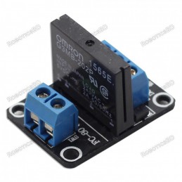
Power supply:5VDC/160mA Switching Voltage (VAC):240@2A Isolation: Phototriac
Reference: RBD-0751
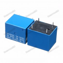
1pcs 12V DC 5pin Relay MODEL: 12VDC WEIGHT: 50.00g DIMENSIONS: 1.80cm x 1.50cm x 1.60cm
Reference: RBD-1180
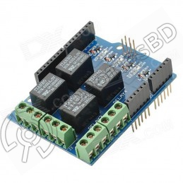
Standard For Shield interfaces and shape Can continue to stack other For expansion boards 3 M3 screw positioning holes for easy installation High Drive (5V or 3.3V) normally open contact closure Onboard relay indicator (red) Note: Relay might be different from the picture as per stock
Reference: RBD-1255
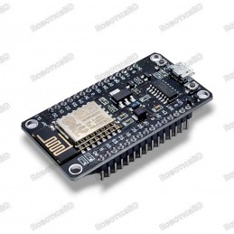
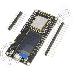
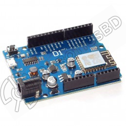
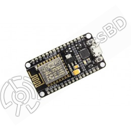
Integrated 0.96″ OLED Micro USB connection Compatible with Arduino Compatible with NodeMCU(Lua for ESP8266) Input Power 5V Compatible for Arduino Compatible with NodeMCU(Lua for ESP8266)A high-quality USB cable is essential for this board to ensure sufficient current supply; otherwise, your board may not be recognized by the Windows Device Manager. Please...
Reference: RBD-1336
Onboard Module: ESP8266 wifi module; in AP mode it can connect with 5 Clients at the same time Operating Way: cellphone carried on wifi module; cellphone and wifi module carried on the same router, and use the APP to control relay Transmission Distance : 400m (max) Relay : 5V,10A/250V AC 10A/30V DC Baud Rate: 9600. Diode effusion protection; Short...
Reference: RBD-1337
Transmission Distance(m) :400 Relay Channel:2 Trigger Voltage (VDC): 5 Switching Voltage (VAC):250@10A Switching Voltage (VDC):30@10A Baud Rate:9600 Note: Relay might be different from the picture as per stock
Reference: RBD-1398
Brand new and high quality. 1-Channel Relay interface board, Equipped with high-current relay : 15A @ 125V AC or 10A @ 250V AC Standard interface that can be controlled directly by microcontroller (Arduino, 8051, AVR, PIC, DSP, ARM) **Relay Brand is different from the picture as per stock
Reference: RBD-1402
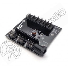
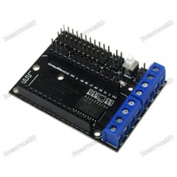
The perfect solution for breaking out the pins from Lua V3 Nodemcu. Lead-out all the IO ports of the ESP-12E development board Lead out the pins of 5V and 3.3V power supply Convenient to connect with peripheral modules Onboard 5V / 1A DC-DC step-down converter circuit Onboard power indicator With DC power jack 6-24V.
Reference: RBD-1602
Microcontroller: ESP8266EX Operating Voltage: 3.3V Digital I/O Pins: 11 (all I/O pins have interrupt/PWM/I2C/one-wire capability, except for D0) Analog Input Pins: 1 Flash Memory: 4MB On-Board Switching Power Supply: Input Voltage Range: 9V to 12V Output: 5V at 1A Max
Reference: RBD-1603
USB-TTL converter. Logic Level: 5V. Operating Supply Voltage: 5V. Digital I/O Pins: 14. Analog I/O Pins: 6.
Reference: RBD-1812
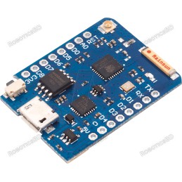
11 digital input/output pins Interrupt/PWM/I2C/one-wire 1 analog input(3.2V max input) 16M bytes(128M bit) Flash External antenna connector Built-in ceramic antenna New CP2104 USB-TO-UART IC
Reference: RBD-1821
Open-source, Interactive, Programmable, Low cost, Simple, Smart, WI-FI enabled Arduino-like hardware IO Integrated TR switch, balun, LNA, power amplifier and matching network Integrated PLL, regulators, DCXO and power management units Onboard USB to serial chip to easily program and upload codes from the Arduino IDE Easy to use breadboard friendly form...
Reference: RBD-2087
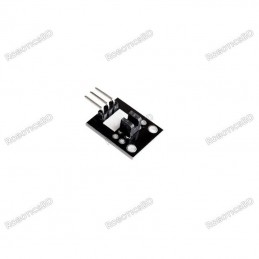
Voltage 5V Photo interruption module triggers a signal when light is blocked between the opening of the sensor.
Reference: RBD-1910
Square onboard USB interface for connection stability The use of imported high-performance USB controller chip Use the special relay driver chip ULN2803, relay work more stable Military grade PCB board production Input voltage: DC 12 V Input Current: more than 300mA Connection : NC / COM / NO Note: Relay might be different from the picture as per stock
Reference: RBD-0189
Brand: DFRobot
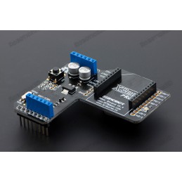
Xbee Shield for Arduino (without Xbee) INTRODUCTION: The XBee Expansion Board is a compliant solution designed to meet low-cost, low-power wireless sensor networks with special needs.The module is easy to use, low power consumption, and the provision of critical data between devices reliable transmission.
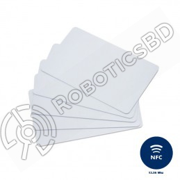
Reference: RBD-0346
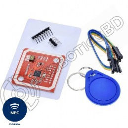
The PN532 is a highly integrated transmission module for contactless communication at 13.56 MHz including microcontroller functionality based on an 80C51 core with 40 Kbytes of ROM and 1 Kbytes of RAM. The PN532 combines a modulation and demodulation concept completely integrated for different kinds of contactless communication methods and protocols at...
Reference: RBD-1670
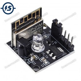
The smallest 802.11b/g/n Wi-Fi SoC module Uses low power 32bit CPU and compatible with the application processor Main frequency up to 160MHz Built-in 10Bit high precision ADC Support UART/GPIO/PWM/ADC interface Integrate Wi-Fi MAC/BB/RF/PA/LNA
Reference: RBD-0028
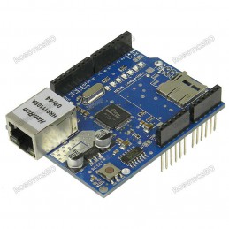
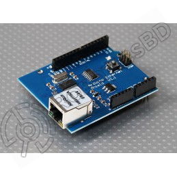
Based on the W5100Based on the Wiznet W5100 allows an Arduino board to connect to the internet. Stackable Design, can directly be supported by for Arduino official Ethernet Library. Supports up to four simultaneous socket connections Can be used to store files for serving over the network. Can be accessed using the Mini SD TF library. IEEE802.3af...
Reference: RBD-2157
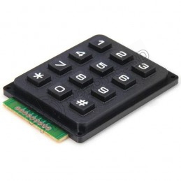
Easy communication with any microcontroller. Tactile type switches. Over 1,000,000 operations per key. Contact rated for 12V dc @ 20mA. Over 1,000,000 operations per key.
Reference: RBD-0937
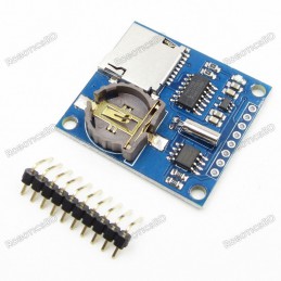
SD card interface works with FAT16 or FAT32 formatted cards. 3.3v level shifter circuitry prevents damage to your SD card. Real-time clock (RTC) keeps the time going even when the Arduino is unplugged. The battery backup lasts for years. Included libraries and example code for both SD and RTC mean you can get going quickly Prototyping area for soldering...
Reference: RBD-2097
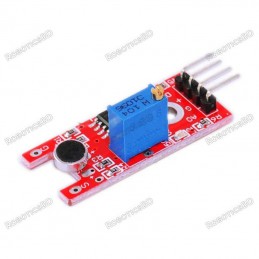
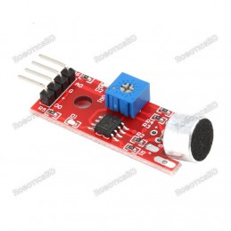
5V Dc Power Supply Power indicator light The comparator output is light High Sensitivity Sound Microphone Sensor Detection Module Electric condenser microphone
Reference: RBD-1541
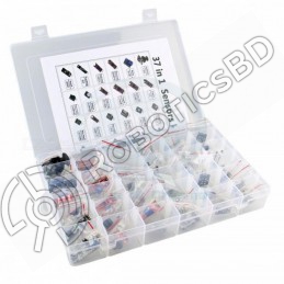
For beginners who are interested in Arduino A complete set of Arduino’s most common and useful electronic components Infrared sensor receiving module Laser sensor module Temperature and humidity sensor module Infrared sensor module 5v relay module Obstacle avoidance sensor module.
Reference: RBD-1137
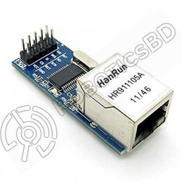
Fully Compatible with 10/100/1000Base-T Networks Integrated MAC and 10Base-T PHY Supports One 10Base-T Port with Automatic Polarity Detection and Correction Supports Full and Half-Duplex modes Programmable Automatic Retransmit on Collision Programmable Automatic Rejection of Erroneous Packets SPI Interface with Clock Speeds Up to 20 MHz For Arduino, SPI,...
Reference: RBD-1180
Standard For Shield interfaces and shape Can continue to stack other For expansion boards 3 M3 screw positioning holes for easy installation High Drive (5V or 3.3V) normally open contact closure Onboard relay indicator (red) Note: Relay might be different from the picture as per stock
Reference: RBD-0392
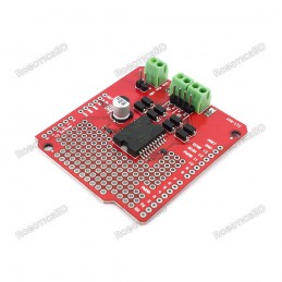
L298P based Arduino motor driver shield Forward, Backward steering indicators Can Drive 2 DC Motors Up to 2A of Maximum Current. RoboticsBD
Reference: RBD-1762
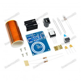
Input voltage(V): 9-12 It can produce high-temperature PCB board size(cm): 3.1 x 4 It is convenient for fans to install high efficiency Weight(g): 20This product is shipped as unassembled and requires soldering to be completed. You will need to do the soldering yourself.
Reference: RBD-2098
Big Microphone Sound Sensor Module Sound Detection Sensor Module High Sensitive Voice Sensor
Reference: RBD-0323
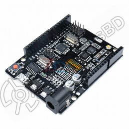
Microcontroller ATmega328 (SMD) – Interface CH340G Operating Voltage: 5V Input Voltage (recommended): 7-12V Digital I / O Pins 14 (of which 6 provide PWM output) RoboticsBD Analog Input Pins: 6 A programming cable is included.
Reference: RBD-2213
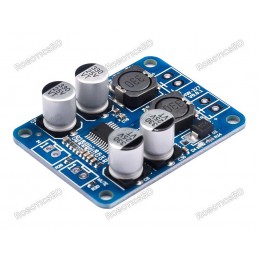
Operating voltage (v):DC 8 – 12V Chipset:TPA3118 - 28 pin Chinese Variant Power output:30W Material:FR4 This is a Chinese variant of the TPA3118 in a 28-pin package.
Reference: RBD-2208
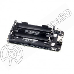
2x 18650 Lithium Battery Shield V8 Mobile Power Expansion Board Module 5V/3A 3V/1A Micro USB for Arduino ESP32 ESP8266 Output port: USB or expansion port Output parameter 5V / 3A or 3.3V / 1A. Conversion efficiency up to 95% Input port: MicroUSB
Reference: RBD-1834
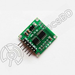
PT100 to 0-5V Converter Voltage Signal Conditioner PCB-mounted
Reference: RBD-0443
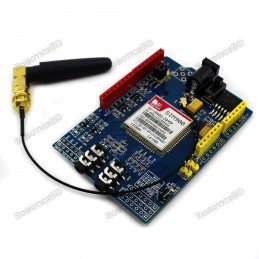
Based on SIMCom‘s SIM900 Module Quad-Band 850 / 900/ 1800 / 1900 MHz - would work on GSM networks in all countries across the world. Control by AT commands - Standard Commands: GSM 07.07 & 07.05 | Enhanced Commands: SIMCOM AT Commands. Short Message Service - so that you can send small amounts of data over the network (ASCII or raw hexadecimal).
Reference: RBD-2094
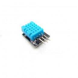
The module can detect the surrounding environment of the humidity and temperature High reliability and excellent long-term stability The output from the digital output Humidity measuring range: 20%~90%RH(0~50 degree (temperature compensation). Temperature measuring range: 0~+50degree. Humidity measurement accuracy: ±5.0%RH. Temperature measurement...
Reference: RBD-1816
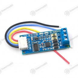
Anti-Interference Ability Baud rate: 110 ~ 256000bps Operating Voltage: 3v to 30VDC Compatible With Both 3V and 5V logic
Reference: RBD-2088
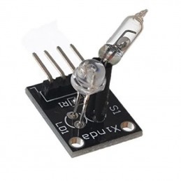
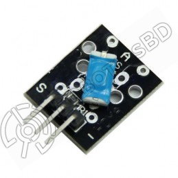
Operating Voltage: 5v DC. This module is Small and Simple to use. Digital switch output (0 & 1) High sensitivity Completes the circuit when the module is tilted LED lights up when tilt switch is activated
Reference: RBD-1218
Model No.:NX8048T050 Display Type:011R(R:Resitive Touchscreen) Operating Voltage (VDC):4.75 ~ 7 Max. Operating Current (mA):410 Touch Type: Resistive Colors:65K (65536)
Reference: RBD-2065
Play standard mono or stereo MP3 files Control with buttons Serial communications protocol (JQ6500 Arduino Library available). Power supply 4.2V Speaker power 4 ohms / 3 watts
Reference: RBD-0399
Power supply voltage: 2.7 V-3.3 V/5 V Data interface level: 2.7-5V. Resolution: 84 x 48 pixel Backlight power supply voltage: highest 3.3 V. Backlight: Blue. RoboticsBD Note: Current stock is tested by us.
Reference: RBD-1417
SMD-MAX7219-MODULE A single module can drive an 8 * 8 common cathode lattice Module Operating voltage: 5V. Module with input and output interfaces Supports multiple modules cascade Led color: Red
Reference: RBD-1810
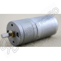
Motor Power Range: 4.5V ~ 36V Control supply range: 4.5V ~ 9V Logical operating current Iss: ≤60mA Driving part of the work current Io: ≤1.2A Maximum power dissipation: 4W (T = 90 ℃) Operating temperature : -25 ℃ ~ + 125 ℃ Drive Type: Dual high-power H-bridge driver
Reference: RBD-2226
Operating Voltage: 24V DC Two separate LEDs for On/Off indication of the Relay Triggering input voltage 3.3V – 5V 4) Back EMF protection Equipped with high-current relay 10A@250VAC / 10A@30VDC It can control both AC and DC appliances such as Solenoids, Motors, lights, fans, etc High-quality screw terminals (Terminal Block) provided (C, NC, NO) for quick...
Reference: 0031
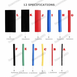
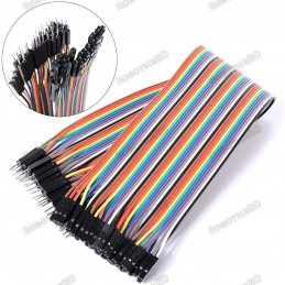
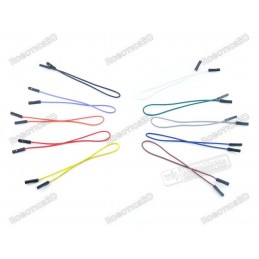
3 Types Available (Please select from option) 1. Male to Male 2. Male to Female 3. Female-Female
Reference: RBD-0694
Power input: 4.5V ~ 9V (10VMAX), USB-powered Transfer rate: 110-460800bps Support UART / GPIO data communication interface Support Smart Link Smart Networking Working temperature: -40°C ~ + 125°C Drive Type: Dual high-power H-bridge Don’t need to download resetting A great set of tools to develop ESP8266 Flash size: 4MByte Lowest cost WI-FI Note: The...
Reference: RBD-1336
Onboard Module: ESP8266 wifi module; in AP mode it can connect with 5 Clients at the same time Operating Way: cellphone carried on wifi module; cellphone and wifi module carried on the same router, and use the APP to control relay Transmission Distance : 400m (max) Relay : 5V,10A/250V AC 10A/30V DC Baud Rate: 9600. Diode effusion protection; Short...
Reference: RBD-0948
Built-in Flash: 32Mbit Power supply: 5V WiFi protocol: IEEE 802.11 b/g/n Peripheral interface: UART/GPIO/ADC/DAC/SDIO/PWM/I2C/I2S Logic level: 3.3V A high-quality USB cable is essential for this board to ensure sufficient current supply; otherwise, your board may not be recognized by the Windows Device Manager. Please avoid using mobile phone cables and...
Reference: 0245
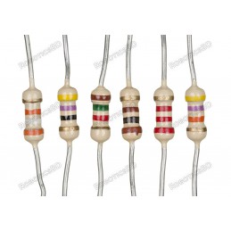
Choose your desire Resistor value from below:
Reference: RBD-0094
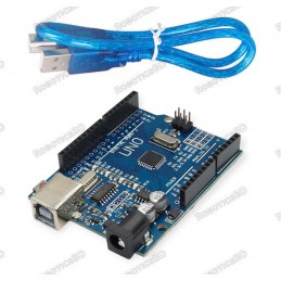
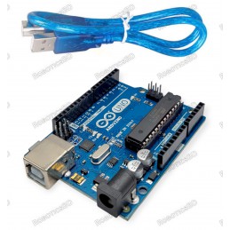
The Arduino Uno R3 High-Quality Edition Arduino UNO in Bangladesh Micro-controller : ATmega328. Operating Voltage : 5V. Input Voltage (recommended) : 7-12V. Digital I/O Pins : 14 (of which 6 provide PWM output). Analog Input Pins : 6. The Arduino Uno R3 High-Quality Edition embodies superior craftsmanship and meticulous attention to detail, resulting in...
Reference: RBD-0028
Based on the W5100Based on the Wiznet W5100 allows an Arduino board to connect to the internet. Stackable Design, can directly be supported by for Arduino official Ethernet Library. Supports up to four simultaneous socket connections Can be used to store files for serving over the network. Can be accessed using the Mini SD TF library. IEEE802.3af...
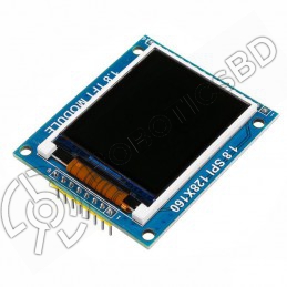
Reference: RBD-0699
Display Size: 1.8″ Driver IC: ST7735 Input Voltage (V): 3.3 to 5 Pixel Resolution: 128 x 160 Interface Type: SPI
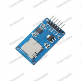
Reference: RBD-0832
Power supply: 4.5V – 5.5V, 3.3V voltage regulator circuit board Positioning holes: 4 M2 screws positioning hole diameter of 2.2mm Control Interface: GND, VCC, MISO, MOSI, SCK, CS Size: 45 x 28mm Net weight: 6g
Reference: RBD-1400
4-Channel Relay interface board and each one needs 15-20mA Driver Current. Both controlled by 12V and 5V input Voltage. Equipped with high-current relay, AC250V 10A ; DC30V 10A. Standard interface that can be controlled directly by microcontroller (Arduino, 8051, AVR, PIC, DSP, ARM, ARM, MSP430, TTL logic active low). Indication LED’s for Relay output...
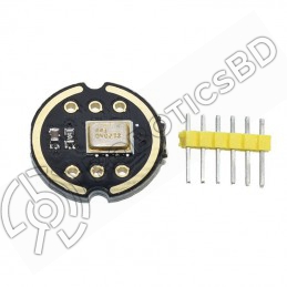
Reference: RBD-1753
Digital I2S interface with high precision 24-bit dataHigh signal to noise ratio is 61 dBAHigh sensitivity – 26 dBFSStable frequency response from 60 Hz to 15 kHzLow power consumption: low current consumption 1.4 mAHigh PSR: -75 dBFS
Reference: RBD-1762
Input voltage(V): 9-12 It can produce high-temperature PCB board size(cm): 3.1 x 4 It is convenient for fans to install high efficiency Weight(g): 20This product is shipped as unassembled and requires soldering to be completed. You will need to do the soldering yourself.
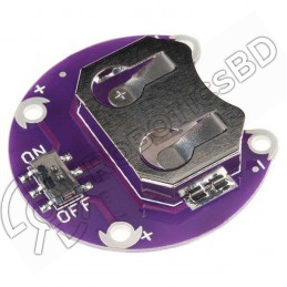
Reference: RBD-2042
Model: LilyPad Color: Purple Material: CCL Dimensions: 30 x 30 x 6 (LxWxH) mm. Weight: 3 gm.
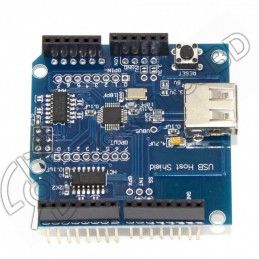
Reference: RBD-0108
Works with standard (dual 5/3.3V) and 3.3V-only (for example, Pro Arduino) boards. Complies with USB Specification Revision 2.0 (Full-Speed 12Mbps Peripheral, Full-/Low-Speed 12Mbps/1.5Mbps Host) Supports HID devices, such as keyboards, mice, joysticks, etc. Compatible with Mass storage devices, such as USB sticks, memory card readers, external hard...
Note: Relay might be different from the picture as per stock