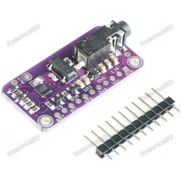
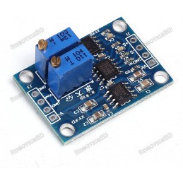
DESCRIPTION
The MCP4725 module is a precision 12-bit Digital-to-Analog converter with I2C interface for adding a true analog voltage output to Arduino and other MCUs.
PACKAGE INCLUDES:
- MCP4725 12-Bit DAC Module
- Male header strip
KEY FEATURES OF MCP4725 12-BIT DAC MODULE:
- 12-bit digital-to-analog conversion
- Single output channel can drive up to 25mA
- Rail-to-rail output swing
- Output setting time is 6uS
- Built-in EEPROM to save settings during power cycle
- 3.3V and 5V logic compatible.
One of the annoying things about most MCUs is that they do not contain a true analog output. Instead they provide PWM which simulates an analog voltage output by switching a digital output on and off rapidly at different duty cycles. This works fine for many applications, but sometimes you need an actual analog voltage output that is computer controlled. That is where this module comes in.
DAC Output
The 12-bit single output provides 4096 steps of resolution. For a VCC of 5V, the step size will be 5V/4095 = 1.22mV.
Typical settling time of the output is 6uS. This is the time from when a new value is written into the device until the output voltage reaches the new value.
The maximum amount of current that the output can sink or source is 25mA. The output can be used to directly drive lower current applications or it can be buffered to provide a higher current capability or to allow the voltage to swing both positive and negative.
I2C Interface
Setting I2C Address
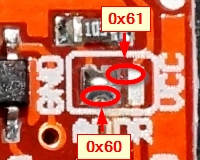
I2C Address Jumpers
The module has an easy to use I2C interface that can be configured to use one of two different I2C addresses if you want to use multiple modules in the same system or if you run into an address conflict with another device.
The address is set by bridging 2 of the 3 small solder pads on top of the module marked ‘ADDR’. The center pin is attached to the A0 address pin on the MCP4725 chip. Next to it are a GND and a VCC pin. A solder blob is used to bridge either the ground or VCC to the A0 pin thus either pulling it to ground via a 10K resistor or tying it to VCC.
As-shipped, the GND and center pin are bridged and so the A0 pin is grounded and the default I2C address is 0x60 as shown in the picture to the right.
If it is desired to change the address, the solder blob can be removed and the center pin and the VCC pin can be bridged with solder instead.
I2C Pull-Up Resistors
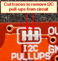
I2C Pull-Up Resistor Cut Straps
The module includes two 4.7K pull-up resistors on the I2C SCL and SDA lines.
If you are hooking up two of these boards on the same I2C bus, these resistors may need to be removed from all but one of the modules if the communications act flaky, but in our testing it hasn’t been necessary.
If it is necessary to remove the pull-up resistors, there are 3 small pads on the back of the board with traces connecting them. To disconnect the pull-ups cut the both trace between the pads. Alternatively the two 4.7K resistors labeled “472” on the top of the board can be removed.
If you decide later to reconnect the pull-ups, simply bridge the 3 pads with some solder.
EEPROM
The MCP4725 includes a built-in EEPROM that can be used to save the settings when the device is powered down. This includes the data value for the DAC output which can be handy in some applications because it allows the device to power up and output a particular voltage without needing to be reprogrammed by an MCU. This can be important if the device is being used to provide a calibration voltage or something similar.
Note that EEPROMs have finite write cycles, typically around 20,000 or so and doing the programming takes a little time. For that reason values should only be programmed into the EEPROM when it is important to remember them and not just do it every time the DAC values are updated if they are being updated continually.
Module Assembly
This module comes with the header loose. This allows you to configure the module to meet your particular requirements such as which side of the board you want the header on or if you want to solder on wires to make the connections.
For use with breadboards, we put the headers on the bottom so that the module can plug directly into the breadboard.
If you are working with the module using an O’Scope, you may find it handy to separate the header into two pieces and place the 2-pins for the output voltage and ground connections on top of the board for easy hook-up using O-scope probes while placing the other 4-pins on the bottom of the module.
Module Connections
The connections to the module are fairly simple.
- Supply 3.3 or 5V power and ground.
- Connect I2C SCL and SDA lines to same on the MCU.
- Hookup the analog output to an O’Scope or whatever you are looking to drive with it.
1 x 6 Header
- OUT = DAC analog output
- GND = Ground point for analog output. It is common with the MCU ground
- SCL = I2C SCL connects to MCU I2C SCL
- SDA = I2C SDA connects to MCU I2C SDA
- VCC = Power and reference voltage for DAC (2.5 to 5.5V)
- GND = Ground connects to MCU ground
Some info on the internet suggest using digital outputs of an MCU to provide VDD and ground for the module by driving the outputs high and low respectively. While this can be done, it limits the output swing to be between what a logic LOW and logic HIGH voltage is. Also keep in mind that VDD is also the reference voltage for the DAC, so noise on this or the ground can affect the accuracy of the output.
OUR EVALUATION RESULTS:
These modules have good build quality and are very useful for creating a fairly precise analog voltage.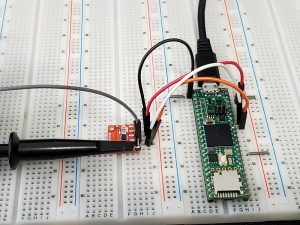
Getting up and running with a basic setup is easy with these modules using the Adafruit_MCP4725 library as shown in the example below. There are a couple of example files that are installed when the library is installed. The library can be easily installed from within the IDE.
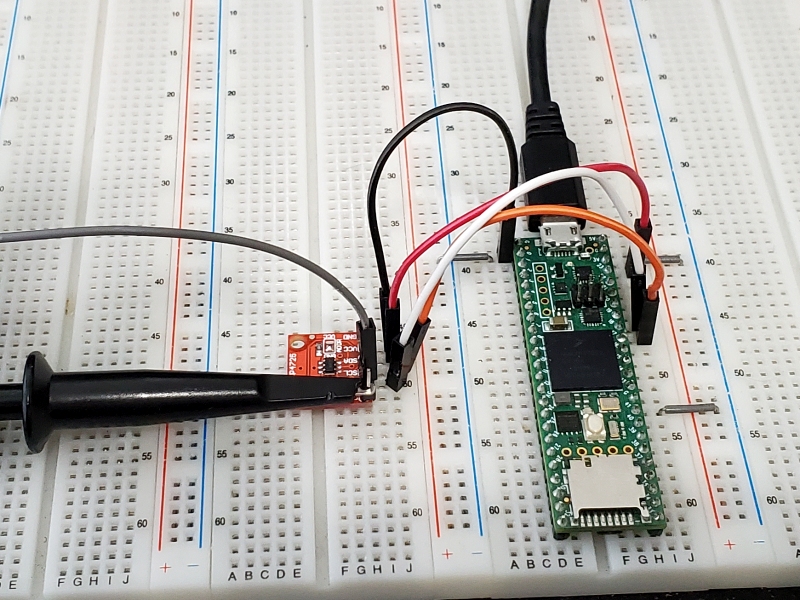
This test setup just requires the connections shown below. We are hooking up the DAC output to a O’scope input in our case. You could also use it to drive an LED with a series current limiting resistor and adding a delay between each DAC write to slow things down enough to easily see it.
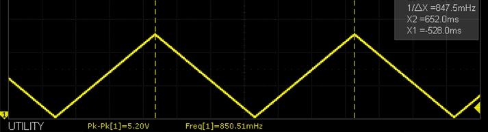
The output of the program as written creates a triangle wave on the output by just ramping the DAC voltage up and then back down through its full range. The resultant frequency in our Uno setup results in a triangle wave with a frequency of a little less than 1Hz as shown below.
The program we are using is a slightly modified version of one of the sample programs ‘trianglewave’ that comes with the library.
MCP4725 12-Bit DAC Module Test Program
/*  MCP4725 12-bit DAC Test Program

    Basic code to test the MCP4725 DAC Module.  Simply ramps the output
    up and down through its full range to give a triangle waveform output.

    Module connections:
      VCC = 3.3 or 5V to match MCU
      Gnd = Ground
      SCL = SCL on MCU
      SDA = SDA on MCU
      OUT = Connects to measurement device

    Uses Adafruit MCP4725 library which can be downloaded via IDE
*/
#include <Wire.h>
#include <Adafruit_MCP4725.h>

Adafruit_MCP4725 dac;
//===============================================================================
//  Initialization
//===============================================================================
void setup(void) {
  dac.begin(0x60);   // Set I2C address to default 0x60
}
//===============================================================================
//  Main
//===============================================================================
void loop(void) {
    uint32_t count;
    // Cycle through the full 12-bit scale to create a triangle wave
    for (count = 0; count < 4095; count++)  // Ramp UP
    {
      dac.setVoltage(count, false);         // Set DAC voltage value.
    }                                       // False = Don't save setting in EEPROM
    for (count = 4095; count > 0; count--)  // Ramp DOWN
    {
      dac.setVoltage(count, false);
    }
}