
Product Images are shown for illustrative purposes only and may differ from the actual product.


 Store Pickup Available!
 Free Ship Over 5000 BDT
 Quality Product
 No Warranty
 No Replacement
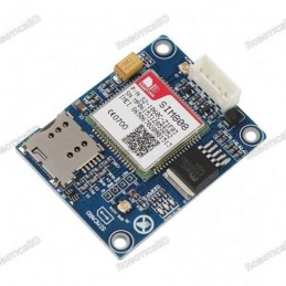
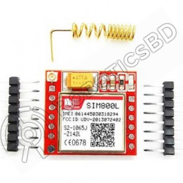
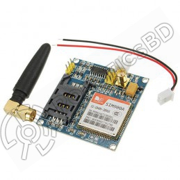
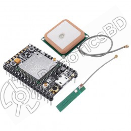
A6 GSM/GPRS module is a miniature GSM modem, which can be integrated into a great number of IoT projects. You can use this module to accomplish almost anything a normal cell phone can; SMS text messages, Make or receive phone calls, connecting to internet through GPRS, TCP/IP, and more! To top it off, the module supports quad-band GSM/GPRS network, meaning it works pretty much anywhere in the world. RoboticsBD
Though the module can work on 5V, the operating voltage of the chip is from 3.3V to 4.2V. To keep supply voltage safe at 4.1V, the module comes with a high frequency step-down switching regulator MP1584 from Monolithic Power Systems – capable of handling load currents up to 3A. Featured By RoboticsBD.
Product Images are shown for illustrative purposes only and may differ from the actual product.
RoboticsBD RoboticsBD RoboticsBD RoboticsBD RoboticsBD RoboticsBD RoboticsBD RoboticsBD RoboticsBD RoboticsBD
There’s a SIM socket on the back! Any activated, 2G micro SIM card would work perfectly.
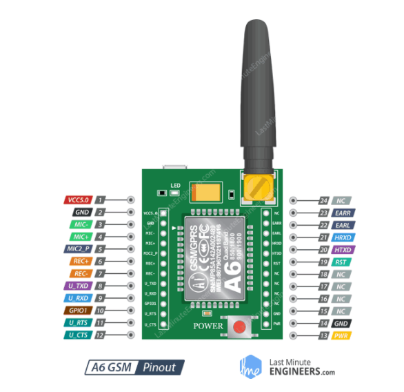
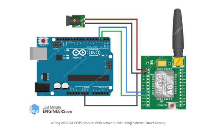
VCC supplies power for the module. Connect this to any external power source rated 5V 2A.
GND is the Ground Pin and needs to be connected to GND pin on the Arduino.
MIC± is a differential microphone input. The two microphone pins can be connected directly to these pins.
MIC2_P pin is used to interface 4-pole TRRS MIC
REC± is a differential speaker interface. The two pins of an 8Ω speaker can be tied directly to these two pins.
U_TxD (Transmitter) pin is used for serial communication.
U_RxD (Receiver) pin is used for serial communication. RoboticsBD
GPIO1 is used to control the module to enter low-power mode.
U_RTS (Request to Send) is UART flow control pin allow the receiver and the transmitter to alert each other to their state.
U_CTS (Clear to Send) is UART flow control pin allow the receiver and the transmitter to alert each other to their state.
EAR_R is used to interface 4-pole TRRS Headset
EAR_L is used to interface 4-pole TRRS Headset
HST_RXD HOST UART is a debug UART, which is used for downloading, calibrating, trace and so on. It doesn’t support any AT command. This interface is only used when debugging, RoboticsBD
HST_TXD UART is a debug UART, which is used for downloading, calibrating, trace and so on. It doesn’t support any AT command. This interface is only used when debugging
RST (Reset) is a hard reset pin. If you absolutely got the module in a bad space, pull this pin low for 100ms to perform a hard reset.
NC Not Connected
PWR pin is used for turning module ON/OFF programmatically. For doing this you must pull it HIGH for a moment (less than 500 ms or around). RoboticsBD
Warning: You should be very careful to not to disconnect the GND before the VCC and always connect GND before VCC. Otherwise the module can use the low voltage serial pins as ground and can get destroyed instantly. RoboticsBD
RoboticsBD RoboticsBD RoboticsBD RoboticsBD RoboticsBD RoboticsBD RoboticsBD RoboticsBD RoboticsBD RoboticsBD
| General Specification | |
| Standby Current | 3 mA |
| Input Voltage | 5 V |
| GSM/GPRS Band Frequency | 850~1900 MHZ |
| Working Temperature Range (°C) | -30 to 80 |
| Safe Input Voltage | 4.1 V |
| Shipment Weight | 0.015 kg |
| Shipment Dimensions | 5 × 3 × 1 cm |
Please allow 5% measuring deviation due to manual measurement.
RoboticsBD RoboticsBD RoboticsBD RoboticsBD RoboticsBD RoboticsBD RoboticsBD RoboticsBD RoboticsBD RoboticsBD
1 x A6 GPRS GSM Module.
RoboticsBD RoboticsBD RoboticsBD RoboticsBD RoboticsBD RoboticsBD RoboticsBD RoboticsBD RoboticsBD RoboticsBD
RoboticsBD RoboticsBD RoboticsBD RoboticsBD RoboticsBD RoboticsBD RoboticsBD RoboticsBD RoboticsBD RoboticsBD
The latest price of A6 GPRS GSM Module in Bangladesh is BDT 900 You can buy the A6 GPRS GSM Module at best price from our RoboticsBD or visit RoboticsBD Office.
|
Please note that the product information provided on our website may not be entirely accurate as it is collected from various sources on the web. While we strive to provide the most up-to-date information possible, we cannot guarantee its accuracy. We recommend that you always read the product labels, warnings, and directions before using any product. |
|
Product Images are shown for illustrative purposes only and may differ from the actual product. |

Reference: RBD-0443
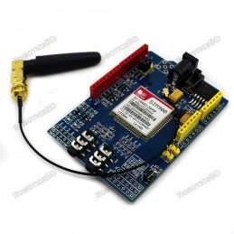
Based on SIMCom‘s SIM900 Module Quad-Band 850 / 900/ 1800 / 1900 MHz - would work on GSM networks in all countries across the world. Control by AT commands - Standard Commands: GSM 07.07 & 07.05 | Enhanced Commands: SIMCOM AT Commands. Short Message Service - so that you can send small amounts of data over the network (ASCII or raw hexadecimal).
Reference: RBD-0552
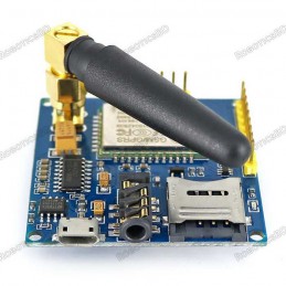
Working frequency: quad-band network, 850 / 900 / 1800 / 1900MHz Working voltage: 4.8-9VDC(On-board voltage regulator circuit supply power for A6 module) Working Current: maximum of 2A. RoboticsBD
Reference: RBD-0579
Quad-band 850/900/1800/1900MHz GPRS multi-slot class12 connectivity: max. 85.6kbps(down-load/up-load) GPRS mobile station class B Controlled by AT Command (3GPP TS 27.007, 27.005 and SIMCOM enhanced AT Commands) Supports charging control for Li-Ion battery Supports Real-Time Clock Integrated GPS/CNSS and supports A-GPS Low power consumption, 10mA in sleep...
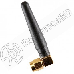
Reference: RBD-1020
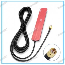
Frequency (MHz) : 824 – 960 MHz & 1710 – 1980 MHz Gain:2 / 3 dBi Impedance (Ω): 50 Connector Type: SMA Plug VSWR :< 2.5
Reference: RBD-1039
The module was recycled from a mobile phone so you can say it is used. TTL serial port for serial port, you can link directly to the micro-controller. Don’t need MAX232. Power module automatically boots, homing network. Onboard signal lights all the way. It flashes slowly when there is a signal, it flashes quickly when there is no signal. In recent years...
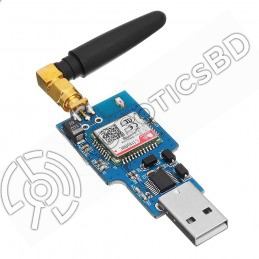
Reference: RBD-1557
USB communication, no need write code Support PC software automation Double antenna Support quad-band, universal worldwide Support 2G/3G/4G Automatically connect to the network Adaptive frequency
Reference: RBD-1641
Product: GSM Antenna Color: Black SMA male straight 5cm 900-1800MHz radio antenna. Frequency: 900MHz – 1800MHz Maximum Power: 50W Length: 5cm/1.97 inch
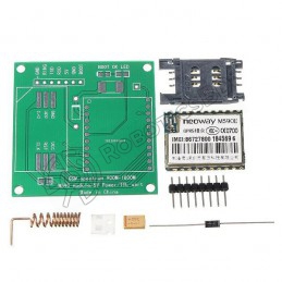
Reference: RBD-1134
Easy to Assemble Comes With all Components Operating Voltage: 5VDC Operating Current: 200mA Compatible With Arduino and Raspberry Pi
Reference: RBD-0273
Brand: Waveshare
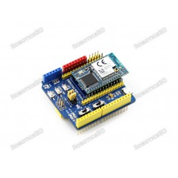
A1rduino WIFI Shield EMW3162 (module is not included)
Reference: RBD-2266
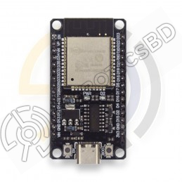
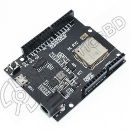
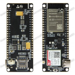
Versatile and powerful development board for IoT and embedded systems projects. USB Type-C port for reversible plug orientation and easy connection to computer or other devices. Built-in Wi-Fi and Bluetooth module for wireless connectivity. Arduino IDE compatibility for easy code writing and uploading. Suitable for a wide range of applications, including...
Reference: RBD-1820
38 Pin version 2.4GHz Dual-Mode WiFi + Bluetooth Development Board, 38PIN Ultra-Low power consumption works perfectly with the IDE A high-quality USB cable is essential for this board to ensure sufficient current supply; otherwise, your board may not be recognized by the Windows Device Manager. Please avoid using mobile phone cables and instead use the...
Reference: RBD-1176
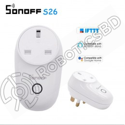
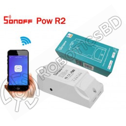
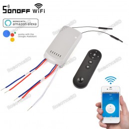
Power supply: 90V~250V AC(50/60Hz) Max. Current: 10A Remote turn on/off connected device. Support checking real-time device status on APP. Support scheduled/countdown/loop timing tasks. Setting scene to turn on/off a group of devices in the same account. Setting scene to trigger on/off the other device by status changes
Reference: RBD-1661
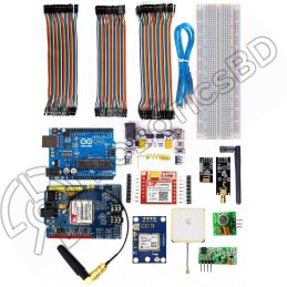
All in one kit for Arduino Based Wireless and IoT NRF wireless Transceiver Module Sim900 Shield Sim800L RF Transmitter and Receiver
Reference: RBD-0960
Voltage range: 100-240V AC Color: White Remote Control Monitor Energy Usage Historical Energy Consumption Overload Protection Measure Power Usage for a Period Sync Status Timing Function Share Control Smart Scene APP Supported Check out New Product Sonoff POWR320D Elite Smart Power Meter Switch
Reference: RBD-1962
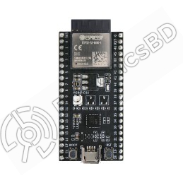
ESP32-S2-DevKitM-1 Equipped with ESP32-S2-MINI-1 module Easy interfacing Integrates ESP32-S2FH4 chip. PCB antenna 4 MB SPI flash.
Reference: RBD-1821
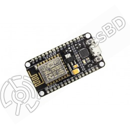
Open-source, Interactive, Programmable, Low cost, Simple, Smart, WI-FI enabled Arduino-like hardware IO Integrated TR switch, balun, LNA, power amplifier and matching network Integrated PLL, regulators, DCXO and power management units Onboard USB to serial chip to easily program and upload codes from the Arduino IDE Easy to use breadboard friendly form...
Reference: RBD-0814
The 2021 Model is Sonoff Basic R2 Support remotely turn on or off added devices. Support Max 8 timers tasks for each added device. Works with AMAZON ALEXA Works with GOOGLE ASSISTANT Also, Work with NEST Support numerous Wi-Fi smart switches one smartphone.
Reference: RBD-1402
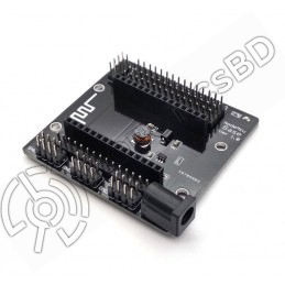
The perfect solution for breaking out the pins from Lua V3 Nodemcu. Lead-out all the IO ports of the ESP-12E development board Lead out the pins of 5V and 3.3V power supply Convenient to connect with peripheral modules Onboard 5V / 1A DC-DC step-down converter circuit Onboard power indicator With DC power jack 6-24V.
Reference: RBD-2219
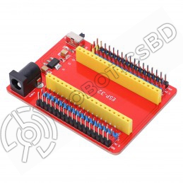
ESP32-IO shield Compatible with RoboticsBD ESP32 Core board Brings out all the pins of RoboticsBD ESP32 Core board 2 rows of 2.54mm pin headers for connecting other sensors Power supply circuit for RoboticsBD ESP32 Core board DC 7-12V voltage input DIP switch for controlling the power
Reference: RBD-1604
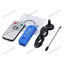
Supports Digital terrestrial video and radio program recording (records digital terrestrial TV on PC or Laptop). The included Input Terrestrial Antenna will offer stable TV signal. Supports Real Time digital video recording and broadcasting. Supports Watching DVB-T digital TV and listen to DAB and FM radio. Full DVB-T bandwidth reception (at 6 / 7 /...
Reference: RBD-2138
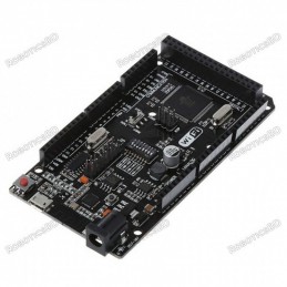
Arduino compatibility Full integration USB-TTL converter 32 Mb flash memory Dual microcontrollersA high-quality USB cable is essential for this board to ensure sufficient current supply; otherwise, your board may not be recognized by the Windows Device Manager. Please avoid using mobile phone cables and instead use the recommended cable available here:...
Reference: RBD-2137
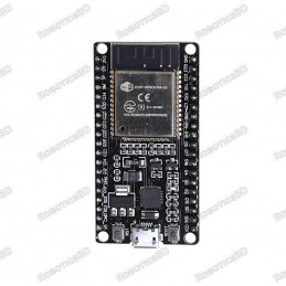
ESP32 Development Board Integrated antenna and RF balun Dual-mode Wi-Fi and Bluetooth chips Small size and high performance-price ratio Compatible with Arduino
Reference: RBD-0318
This module is intended for advanced users who require moderate knowledge of GSM systems and microcontrollers. It needs wiring and firmware updates to unlock the country lock. Dual-Band 900/ 1800 MHz GPRS multi-slot class 10/8GPRS mobile station class B Compliant to GSM phase 2/2+ Dimensions: 24*24*3 mm Weight: 3.4g Control via AT commands (GSM 07.07...
Reference: RBD-0698
On-board level shift circuit Arduino UNO R3 and the compatible board can directly connect to this module; Interface logic voltage: 3.3V / 5V compatible(On-board level shift circuit); Working voltage: 4.5~5.5V (Onboard 3.3V LDO Regulator); Working current: 240mA(MAX).RoboticsBD
Reference: RBD-1640
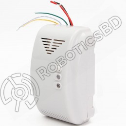
Color: White Material: Metal + Plastic Operating Voltage : 12V DC Standby Current : ≤90mA Alarm Current : ≤100mA
Reference: RBD-1526
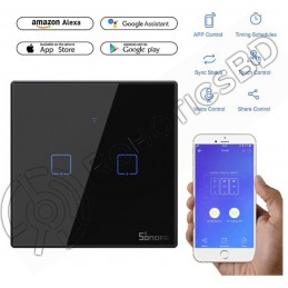
Can control up to 2 device 220V Model : T3EU2C Remotely control devices through a phone Turn on/off devices with Amazon Alexa and Google Assistant Touch control buttons for convenient operation Set a particular time to turn on/off devices Customize one or groups of SONOFF devices to turn on/off with a simple tap Allow you to manage devices when there is...
Reference: RBD-1017
Input: AC 100-240V 50/60 Hz 5A Output: Light: AC 100-240V 50/60 Hz 3A, Fan: AC 100-240 V 50/60 Hz 2A Max Rf Frequency: 433.92 MHz Turn on/off ceiling fan and light using your voice Support the RM433 RF to control devices (RM433 RF included) Share the device and manage it with your family together Display the real-time device status on the app Check out...
Reference: RBD-1412
Chipset :ESPRESSIF-ESP32 240MHz Xtensa® single-/dual-core 32-bit LX6 microprocessor FLASH: QSPI flash 4MB / PSRAM 8MB SRAM:520 kB SRAM Button: Reset USB to TTL: CP2104 Modular interface: UART,SPI,SDIO,I2C,PWM,TV PWM,I2S,IRGPIO On-board clock:40MHz crystal oscillator Working voltage:2.7V-3.6V Working current: About 70mA
Reference: RBD-2142
Operating Voltage: 5VDC USB to Serial Converter: CH340C Compatible With:ESP8266 ESP-01/01S Comes With Onboard Reset Switch Has Female Headers for Connecting the Wifi Module.
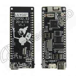
Reference: RBD-1945
TTGO module from LilyGO Microcontroller based on an ESP32-S2 chip. USB-C connection MicroSD card adapter.
Reference: RBD-2271
Wide compatibility with ESP32-DevKitC(30P) series boards Safe and reliable with stable power and signal transmission Extended GVS interface for easy connection to various electronic modules and sensors JUMP interface for easy reuse of all pins, making it ideal for DIY projects Versatile and reliable option suitable for a wide range of projects
Reference: RBD-0697
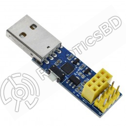
Driver Chip: CH340G Supports all basic windows versions. The adapter plate integrated 1000μF solid capacitors to ensure the current supply The power supply will not be a problem to make WIFI module crashes unresponsive. Using 3225 SMD crystal oscillator, improve the stability of serial work, on a beautiful and tall. Working voltage: 4.5V – 5.5V (Onboard...
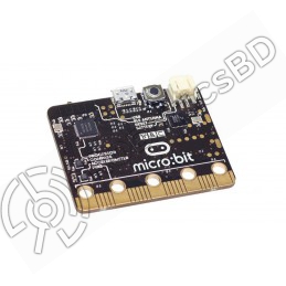
Reference: RBD-1864
USB and Bluetooth Low energy connectivity. Compass and Accelerometer. 2 x user-assignable buttons. A 25 LED display. 21 pin edge connector.
Reference: RBD-2270
Powerful and versatile ESP32 SoC with WiFi and Bluetooth connectivity 4MB of flash memory and 520KB of SRAM for storing firmware and data Compatible with the Arduino development environment for easy programming Input/output pins for connecting to sensors, actuators, and other peripherals Can be programmed using MicroPython, a high-level programming...
Reference: RBD-1015
Power Supply: 90V~250V AC(50/60Hz) Max. Current: 10A/gang Max. Power:2200W/gang, 2200W/Total Wireless Standard: 802.11 b/g/n Security Mechanism: WPA-PSK/WPA2-PSK Enclosure Material: Fire-retardant ABS V0
Reference: RBD-0948
Built-in Flash: 32Mbit Power supply: 5V WiFi protocol: IEEE 802.11 b/g/n Peripheral interface: UART/GPIO/ADC/DAC/SDIO/PWM/I2C/I2S Logic level: 3.3V A high-quality USB cable is essential for this board to ensure sufficient current supply; otherwise, your board may not be recognized by the Windows Device Manager. Please avoid using mobile phone cables and...
Reference: RBD-1831
Part No: 6ED1052-1MD08-0BA1 Country of origin: China Condition: Brand New
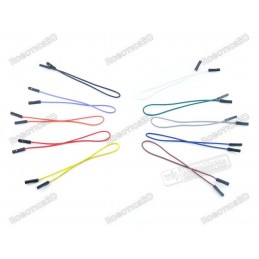
Reference: 0031
3 Types Available (Please select from option) 1. Male to Male 2. Male to Female 3. Female-Female
Reference: RBD-1039
The module was recycled from a mobile phone so you can say it is used. TTL serial port for serial port, you can link directly to the micro-controller. Don’t need MAX232. Power module automatically boots, homing network. Onboard signal lights all the way. It flashes slowly when there is a signal, it flashes quickly when there is no signal. In recent years...
Reference: RBD-0694
Power input: 4.5V ~ 9V (10VMAX), USB-powered Transfer rate: 110-460800bps Support UART / GPIO data communication interface Support Smart Link Smart Networking Working temperature: -40°C ~ + 125°C Drive Type: Dual high-power H-bridge Don’t need to download resetting A great set of tools to develop ESP8266 Flash size: 4MByte Lowest cost WI-FI Note: The...
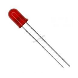
Reference: RBD-0768
Size: 5mm Color: RED Head Shape: Round Lens Appearance: Transparent
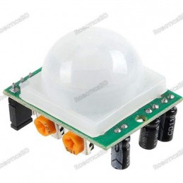
Reference: RBD-0023
Wide Working Voltage Range: DC 4.5V- 20V Current Drain: <60uA Detection Angle: <140° Detection Distance: 3 to 7m (can be adjusted) Blockade time: 2.5s (Default) Work temperature: -20-+80°C
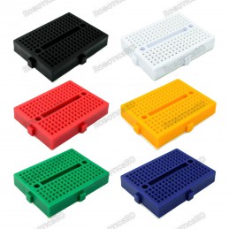
Reference: RBD-0280
Tie-points: 170 (10×17) Size: 48 x 35 x 10 mm(LxWxH). Use: experimental, testing, robot Matching jumper, diameter 0.8mm Phosphor bronze nickel plated spring clips Accepts a variety of wire sizes (29-20 the AWG) **1 pcs Random Color
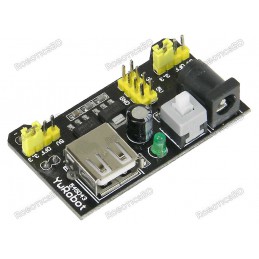
Reference: RBD-0549
Breadboard power supply module, compatible with 5V, 3.3V. RoboticsBD Apply to MB102 breadboard Input voltage: 6.5-12 V (DC) or USB power supply Output voltage: 3.3V/5V can switch over Maximum output current: <700 ma Fluctuation two road independent control can switch over to 0 V, 3.3 V, 5 V On-board two groups of 3.3V, 5V DC output plug pin, convenient...
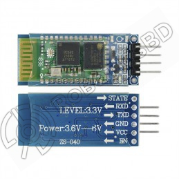
Reference: RBD-0040
Bases at CSR BC04 Bluetooth technology. with build-in 2.4GHz PCB antenna It’s at the Bluetooth class 2 power level. Range test: 10 meters Operating voltage: 3.3V to 6V DC Operating current in pairing is in the range of 30~40mA.
Reference: RBD-0318
This module is intended for advanced users who require moderate knowledge of GSM systems and microcontrollers. It needs wiring and firmware updates to unlock the country lock. Dual-Band 900/ 1800 MHz GPRS multi-slot class 10/8GPRS mobile station class B Compliant to GSM phase 2/2+ Dimensions: 24*24*3 mm Weight: 3.4g Control via AT commands (GSM 07.07...
Reference: RBD-0694
Power input: 4.5V ~ 9V (10VMAX), USB-powered Transfer rate: 110-460800bps Support UART / GPIO data communication interface Support Smart Link Smart Networking Working temperature: -40°C ~ + 125°C Drive Type: Dual high-power H-bridge Don’t need to download resetting A great set of tools to develop ESP8266 Flash size: 4MByte Lowest cost WI-FI Note: The...
Reference: RBD-2138
Arduino compatibility Full integration USB-TTL converter 32 Mb flash memory Dual microcontrollersA high-quality USB cable is essential for this board to ensure sufficient current supply; otherwise, your board may not be recognized by the Windows Device Manager. Please avoid using mobile phone cables and instead use the recommended cable available here:...
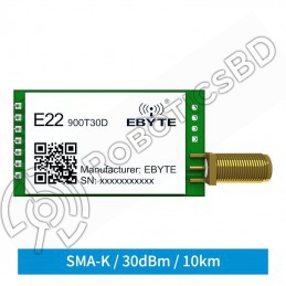
Reference: RBD-2176
LoRa module based on Semtech SX1262 RF chip Supports automatic relay networking Long transmission distance up to 10 km Low power consumption Small size
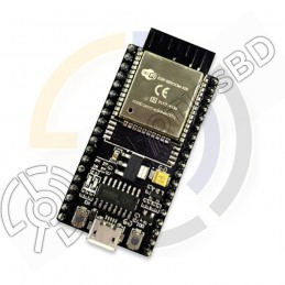
Reference: RBD-2268
Features WiFi+Bluetooth connectivity with the ESP-WROOM-32 module Accessible I/O pins via extension headers for easy customization Onboard USB CH340 for convenient programming and debugging 2x keys for reset or user-defined functions ESP32S-DEV development board is a cost-effective solution for a wide range of applications.A high-quality USB cable is...
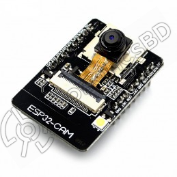
Reference: RBD-1407
Flash LED off: 180mA @ 5V. Flash LED on to maximum brightness: 310mA @ 5V. Deep-sleep: 6mA @ 5V min. Modem-sleep: 20mA @ 5V min. Light-sleep: 6.7mA @ 5V min. Programmer: ESP32-CAM-MB MICRO USB Download Module The ESP32 CAM does not come pre-assembled with the camera. You'll need to connect the camera ribbon cable to the board, a task which can be...
Reference: RBD-0948
Built-in Flash: 32Mbit Power supply: 5V WiFi protocol: IEEE 802.11 b/g/n Peripheral interface: UART/GPIO/ADC/DAC/SDIO/PWM/I2C/I2S Logic level: 3.3V A high-quality USB cable is essential for this board to ensure sufficient current supply; otherwise, your board may not be recognized by the Windows Device Manager. Please avoid using mobile phone cables and...
Reference: RBD-1138
Board Based On AI-Thinker A9 GPRS Module Supports Firmware Upgrade Via Serial Port Operating Voltage: 5v