DESCRIPTION
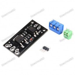
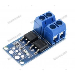
This MOSFET module with optoisolation uses the D4184 N-Channel logic compatible MOSFET with low Rds(on) for moderate to higher current low-side switching applications.
PACKAGE INCLUDES:
- D4184 MOSFET Control Module
- 3-pin Screw Terminal
- 2-pin Screw Terminal
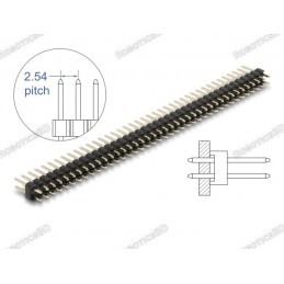
- Small male header strip
KEY FEATURES OF D4184 MOSFET CONTROL MODULE:
- One switching output
- Low 8.5mΩ Rds(on) resistance
- 2.5V – 20V input control voltage with optoisolation
- 6 – 36V output switching voltage
- 10A continuous current handling capability (See notes below)
- 3.3 and 5V logic compatible (See notes below)
The modules utilizes the D4184 N-channel MOSFET that has a low Rds(on) resistance of 8.5mΩ typical.
These modules support about 10A of continuous current with a load voltage of 12V. If driven with PWM, the maximum peak current can be greater up to 20A or more.
The design of these modules includes an optoisolator on the input so the input is biased from the output load voltage and is independent of logic levels used for the drive signal. A 3.3V input will drive as much current as a 5V input for instance.
Note that the module does not have a fly-back diode on the board. If using the module with inductive loads, an external fly-back diode should be used to avoid possible damage.
Theory of Operation
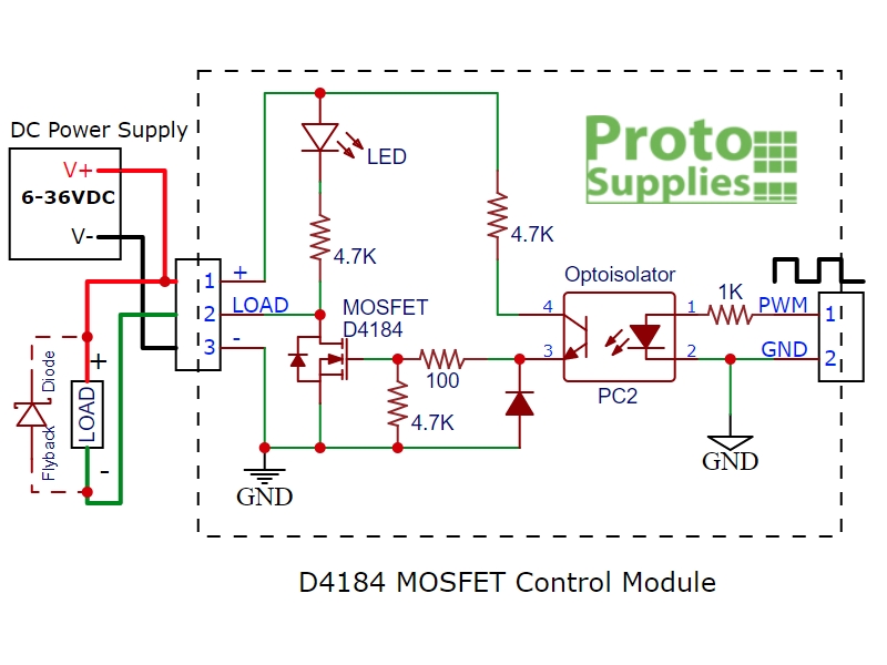
The module includes a PC817 optoisolator which provides electrical isolation between the high powered MOSFET side and the logic signals used to control the module. If something goes wrong and you burn up the MOSFET, it should not damage the MCU being used to control it.
The MCU PWM input to the module drives the internal LED side of the optoisolator. This input includes a 1K ohm series current limiting resistor to keep the current through the LED at safe levels which allows the input to be driven by up to a 20V input or even higher if you are not using an MCU.
When the PWM input signal is low or disconnected, the internal LED in the optoisolator is off which in turn keeps the phototransistor output turned off. With the phototransistor off, the gate of the MOSFET is pulled to ground by a 4.7K resistor. This keeps the MOSFET turned off and the load is disconnected from ground and disbled.
A logic high on the PWM input turns on the internal optoisolator LED which turns on the phototransistor. This creates a voltage divider composed primarily of two 4.7K resistors. This biases the gate at 50% of the power supply voltage which turns on the MOSFET. If a 12V power supply is used, the gate will be at 6V.
Since the maximum gate voltage available to turn on the MOSFET is 50% of the power supply voltage, that limits the power supply to a minimum of about 6V. Power dissipation in the MOSFET will be higher with lower power supply voltages and a minimum power supply of 9V is recommended if trying to draw more than a few amps through the module.
When the MOSFET conducts, the load is connected to ground to complete the circuit and the load is powered up. This also provides a ground for the on-board LED which lights to indicate that the MOSFET is turned on. A 4.7K resistor limits current through the on-board LED to safe levels over the 6-36V operating range.
Module Connections
The module requires 3 connections. A logic signal to turn the MOSFET on/off; a DC power supply to power the device (load) being controlled and finally the load itself. Connectors are provided that can be soldered to be the board, but these connections can also be made by direct wiring if desired.
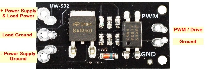
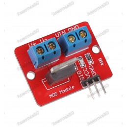
D4148 MOSFET Control Module – Connections
Logic Signal Connections: The 2-pin connector on the right side is for making connections to the MCU. It has two holes on 4mm centers which support a 2 position screw terminal as well as two holes on 0.1″ centers that can alternatively support a standard male header which may be handy in a breadboard setup. The pins are labeled PWM for the signal and GND for the signal ground.
DC Load Power Supply: is connected to the 3-pin screw terminals marked + / LOAD / – on the back of the module. The positive lead of the power supply connects to + and the ground connection is hooked up to –. The module supports a load power supply of 6-36VDC
Load: The load which is being driven is connected to the screw terminals marked + and Load on the back of the module. The positive lead of the load connects to the + terminal and the negative lead of the load connects to – terminal.
The signal ground and the load ground connections are not connected together on the module due to the optoisolator being used to provide isolation between the MOSFET power circuit and the MCU.
1 x 2 Screw Terminal / Header (Logic Signal Input)
- PWM = Signal input (active HIGH).
- GND = Signal ground
1 x 3 Screw Terminal (Load Power Supply Connections)
- + = Connect to power supply (6-36V) being used to power the load
- – = Connect to power supply ground
1 x 3 Screw Terminal (Load Connections)
- + = Connect to positive lead of load (motor, LEDs, fan, etc)
- LOAD = Connect to negative lead of load
Physical Mounting: There are two 2mm diameter holes at the signal end of the board spaced 12mm apart if it is desired to physically mount it.
OUR EVALUATION RESULTS:
These modules work well for basic ON/OFF operation such as for driving a solenoid or PWM control such as for dimming an array of LEDs and can handle a surprising amount of power given the small size. It is also possible to parallel these modules to further increase the power handling capability. Though the maximum current spec for the MOSFET is 50A, do not expect to run 50A through this small module as it will quickly overheat due to minimal heatsink capability of the small PCB.
 One important point to take note of is that if an inductive load is being controlled, an external fly-back diode should be used to prevent possible damage when the load is switched off.
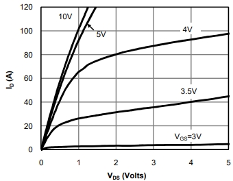
The chart to the right from the datasheet shows the effect of the drive (Gate) voltage on the maximum potential current through the MOSFET device. Since the gate is driven off the load power supply at a 50% level, for a 10V power supply, the current handling will be similar to the 5V curve.
The chart below shows some example temperature measurements of the MOSFET with a load varying from 2.5A to 20A @ 12V. The logic drive signal varies from 100% duty cycle (always on) to 50% duty cycle or 25% duty cycle. The measurements are being taken with no airflow over the module and an ambient temperature of 22C. Since a 12V power supply is being used, the gate voltage is around 6V which gives pretty good performance.
In general, you should keep the MOSFET under about 100°C to keep it happy. For long-term use, 80°C or lower would be a better target.
| Load Amps |
12V Input @ 100% duty cycle |
12V Input @ 50% duty cycle |
12V Input @ 25% duty cycle |
| 2.5A |
32°C |
|
|
| 5A |
39°C |
30°C |
|
| 10A |
69°C |
47°C |
|
| 12.5A |
102°C |
63°C |
43°C |
| 15A |
X |
78°C |
48°C |
| 20A |
X |
115°C+ |
74°C |
BEFORE THEY ARE SHIPPED, THESE MODULES ARE:
- Sample tested per incoming shipment
Notes:
- None
TECHNICAL SPECIFICATIONS
| Maximum Ratings |
|
|
| VDS |
Drain-Source Voltage |
40V max (36V recommended) |
| ID |
Drain Current Max (Continuous) |
10A @ 12V |
| RDS(on) |
Drain-Source On-Resistance |
8.5mΩ |
| Dimensions |
(L x W x H) |
35 x 16 x 14mm (1.38 x 0.63 x 0.55″) |
| Country of Origin |
|
China |
| Datasheet |
|
AOD4184 |